Automatic step ladder

A technology of automatic step ladders and linkage plates, which is applied in escalators, transportation and packaging, etc. It can solve the problems of unsafe hidden dangers, the elderly are struggling to go up and down stairs, and they are easy to fall, so as to achieve convenient operation, solve the difficulty, and prevent accidental falls Effect

Pending Publication Date: 2020-12-04
白书考 +1
View PDF0 Cites 0 Cited by
  • Summary
  • Abstract
  • Description
  • Claims
  • Application Information

AI Technical Summary

Problems solved by technology

[0002] Most of the residents in the existing old community are the elderly. There is no elevator in the old community. It is very difficult for the elderly to go up and down the stairs, and they are prone to falls when going up and down the stairs, which brings unsafe hazards

Method used


Image

  • Automatic step ladder
  • Automatic step ladder
  • Automatic step ladder

Examples


specific Embodiment approach 1

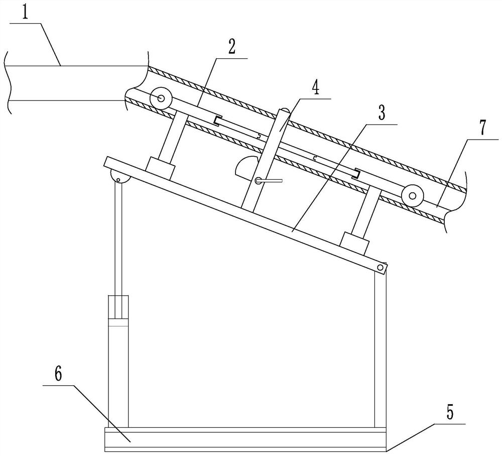
[0020] Specific implementation mode one: as Figure 1 to Figure 9 As shown, this embodiment discloses an automatic step ladder, including a channel steel 1, a rail car 2, a support device 3, a bottom plate 5, a pedal 6, a steel wire 7, a pulley 8 and a hoist 9, and the two sides of the channel steel 1 The wall is relatively bent, and the channel steel 1 is fixedly connected to the ascending stairs, the descending stairs and the wall on one side of the platform on each floor. The rail car 2 is fixedly connected, the lower end of the support device 3 is fixedly connected to the base plate 5, the base plate 5 is connected to the pedal 6 in rotation, and the channel steel 1 is internally rotatably connected to the wheel shaft of the pulley 8 pulley 8 and the channel steel 1 through the bearing Rotation connection, the channel steel 1 is provided with a steel wire 7 inside, the steel wire 7 bypasses the pulley 8, the steel wire 7 is wound on the winch 9, the two ends of the steel w...

specific Embodiment approach 2

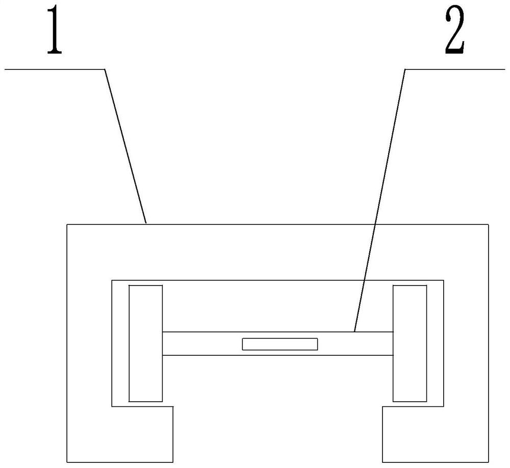
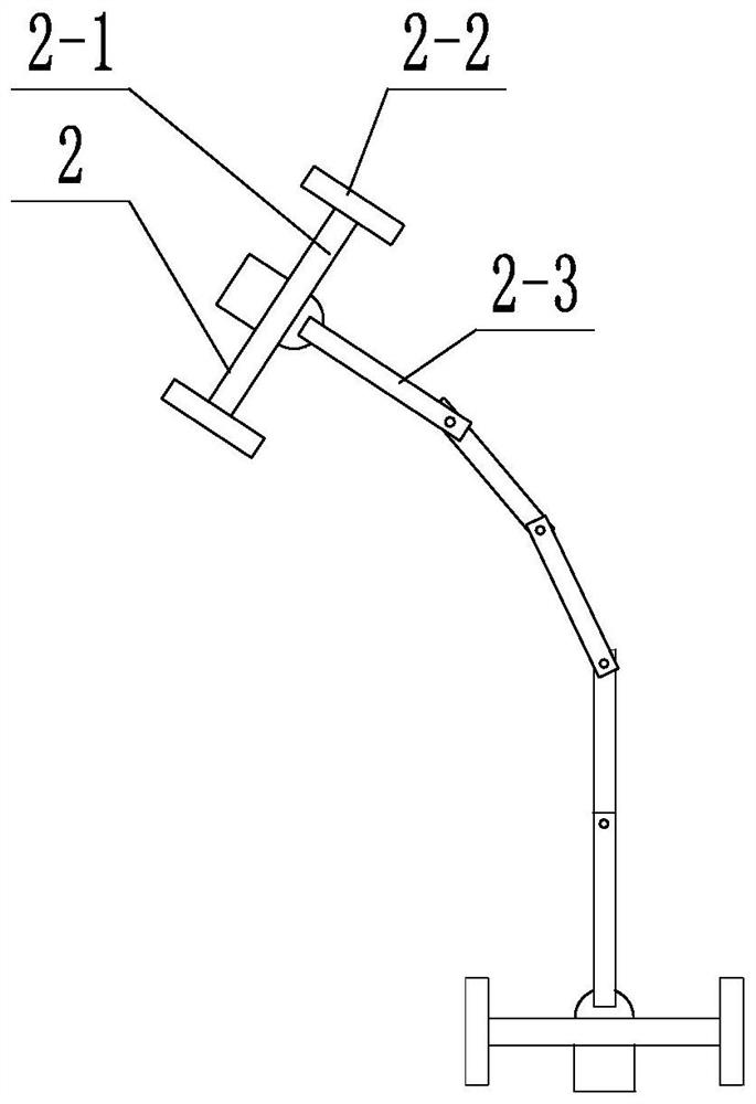
[0021] Specific implementation mode two: as image 3 As shown, this embodiment is a further description of the specific embodiment one. The rail car 2 includes: two axles 2-1, four wheels 2-2 and a plurality of hinge plates 2-3, each of which The two ends of the axle 2-1 are respectively rotatably connected with a wheel 2-2, the plurality of hinged plates 2-3 are arranged sequentially, and each adjacent two hinged plates 2-3 are hinged, and the hinged plates at both ends The plates 2-3 are respectively fixedly connected to the corresponding axles 2-1; the two ends of the steel wire 7 are respectively fixedly connected to the two axles 2-1.

specific Embodiment approach 3

[0022] Specific implementation mode three: as Figure 4 As shown, this embodiment is a further description of specific embodiment 1. The support device 3 includes a linkage plate 3-1, a sleeve 3-4, a sliding column 3-5, a limit column 3-6, two A ball shaft 3-2 and two support columns 3-3, the bottom of the hinge plate 2-3 at both ends is fixedly connected with one end of a support column 3-3 respectively, and the other end of each support column 3-3 is connected to the corresponding One ball shaft 3-2 is fixedly connected, the lower ends of the two ball shafts 3-2 are rotationally connected with the linkage plate 3-1, and the bottom of one end of the linkage plate 3-1 is hinged with a sliding column 3-5, and the sliding column The lower end of 3-5 is slidingly arranged in the sleeve 3-4, and the other end of the linkage plate 3-1 is hinged to the limit column 3-6; the sleeve 3-4 is fixedly connected to the lower end of the limit column 3-6. Bottom plate 5.


PUM


Abstract

An automatic step ladder belongs to the field of elevator devices and comprises channel steel, a rail car, a support device, a bottom plate, a pedal, a steel wire, pulleys and a winch, two side wallsof the channel steel are oppositely bent, the channel steel is fixedly connected onto an ascending stair, a descending stair and a wall surface on one side of a platform of each floor, the rail car isslidably arranged in the channel steel, the upper end of the supporting device is fixedly connected with the rail car, the lower end of the supporting device is fixedly connected with the bottom plate, the bottom plate is rotatably connected with the pedal, the pulleys are rotatably connected inside the channel steel, the steel wire is arranged inside the channel steel, the steel wire winds around the pulleys to be attached to the winch, the two ends of the steel wire are fixedly connected with the rail car, and the winch is fixed in a corridor. The automatic step ladder can solve the problemthat old people are strenuous to go upstairs and downstairs, protects the safety of the old people, has a protection function and further protects the safety of passengers.

Description

technical field [0001] The invention belongs to the field of elevator devices, in particular to an automatic step ladder. Background technique [0002] Most of the residents in the existing old community are elderly people. There is no elevator in the old community. It is very difficult for the elderly to go up and down the stairs. Contents of the invention [0003] The object of the present invention is to provide an automatic step ladder to solve the above-mentioned problems in the prior art. [0004] To achieve the above object, the present invention takes the following technical solutions: [0005] An automatic step ladder, comprising a channel steel, a rail car, a supporting device, a bottom plate, a pedal, a steel wire, a pulley and a hoist, the two side walls of the channel steel are relatively bent, and the channel steel is fixedly connected to the upper floor of each floor Stairs, descending stairs, and the wall on one side of the platform, the rail car is slida...

Claims


Application Information

Patent Timeline
IPC IPC(8): B66B23/08B66B23/02B66B23/00B66B29/00
CPCB66B23/00B66B23/02B66B23/08B66B29/00
Inventor 白书考田文慧
Owner 白书考
Why Eureka
Try Eureka