
A kind of brake for warping machine to stop after warp breakage

A technology of automatic stop and warping machine at warp breakage, applied in warping machines, manufacturing tools, other manufacturing equipment/tools, etc., can solve the problems of difficult to meet the problem of automatic stop at warp breakage, less drum brakes, and inclined brake pads. , to avoid thermal decay and reduce braking performance

Active Publication Date: 2021-08-03
惠州市健新粘扣带有限公司
View PDF0 Cites 0 Cited by
  • Summary
  • Abstract
  • Description
  • Claims
  • Application Information

AI Technical Summary

Problems solved by technology

[0003] The main function of the brake used for warping machines in the prior art is to make the transmission wheel stop quickly to achieve the purpose of self-stopping. At present, the braking methods used are mainly disc type and drum type. The phenomenon of heat attenuation is rarely used now, and the disc brake is similar to the disc brake structure used in automobiles, and the friction between the two brake pads and the transmission wheel is used to achieve braking, but in actual use , due to the lack of a limit device for the two brake pads, the brake pads are prone to tilt after long-term use, and manual adjustment is more troublesome
[0004] Simultaneously, the brake in the existing technology generally only adopts a kind of braking method to brake the transmission wheel, but it is insufficient when facing the equipment of warping machine that needs to stop quickly, it is difficult to use only one braking method Quickly stop the transmission wheel on the warping machine, it is difficult to meet the demand of automatic stop at warp break

Method used


Image

  • A kind of brake for warping machine to stop after warp breakage
  • A kind of brake for warping machine to stop after warp breakage
  • A kind of brake for warping machine to stop after warp breakage

Examples


Embodiment Construction

[0044] The following will clearly and completely describe the technical solutions in the embodiments of the present invention with reference to the accompanying drawings in the embodiments of the present invention. Obviously, the described embodiments are only some, not all, embodiments of the present invention. Based on the embodiments of the present invention, all other embodiments obtained by persons of ordinary skill in the art without making creative efforts belong to the protection scope of the present invention.

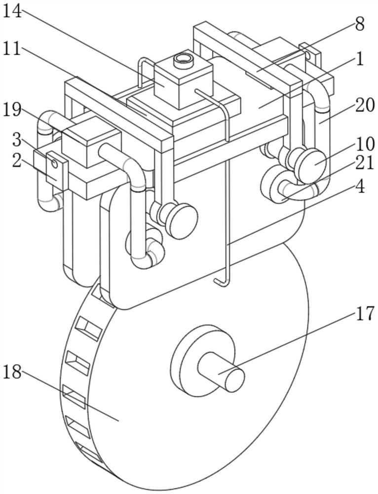
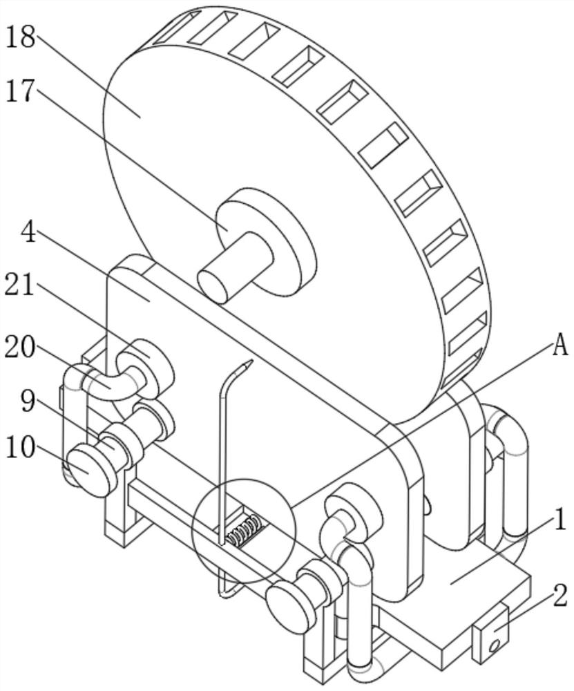
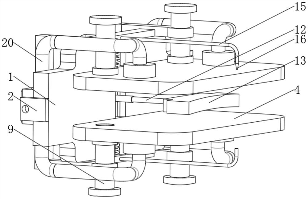
[0045] see Figure 1-5 , a brake for warping warp self-stopping of a warping machine, comprising a top plate 1, characterized in that: a chute 5 is provided in the middle of the bottom end of the top plate 1, and a brake pad 4 is provided at the bottom end of the top plate 1, the number of the brake pads 4 There are two, the bottom ends of the two brake pads 4 are fixedly installed with sliders 6, the brake pads 4 are flexibly clamped between the sliders 6 and...


PUM


Abstract

The invention relates to the technical field of warping machine braking, and discloses a brake for warp breaking and self-stopping of a warping machine, which includes a top plate, a chute is opened in the middle of the bottom end of the top plate, and a brake pad is provided at the bottom end of the top plate. The number of the brake pads is two, and the bottom ends of the two brake pads are fixedly equipped with sliders, and the brake pads are movably clamped between the sliders and the chute. The brake of warp breaking and self-stopping of the warping machine is provided with a chute at the bottom of the top plate, and a slider is fixed at the bottom of the two brake blocks, and the brake block is moved between the slider and the chute. At the same time, the installation rods are fixed on the left and right sides of the front of the brake block, and they are flexibly socketed with the fixed frame, through the movable clamping connection between the chute and the slider and the connection between the fixed frame and the installation rod The movable clamping joint limits the position of the brake pads, thereby realizing the advantage that the position of the brake pads can be limited.

Description

technical field [0001] The invention relates to the technical field of warping machine braking devices, in particular to a warping machine brake that automatically stops when warp breaks. Background technique [0002] The warping machine can be divided into two categories, one is the traditional drum friction transmission warping machine, and the other is the new warping shaft direct transmission warping machine, among them, the pressure method of the drum friction transmission warping It relies on the weight of the heavy hammer, the warp beam arm and the warp beam itself. The old machine adopts the method of horizontal pressure after the transformation, while the new warp beam direct transmission warp yarn is drawn from the bobbin on the creel. , first pass through the gap between the yarn gripper and the column, pass through the broken end detector, pass through the yarn guide porcelain plate forward, then pass through the yarn guide rod, pass through the telescopic reed, ...

Claims


Application Information

Patent Timeline
Patent Type & Authority Patents(China)
IPC IPC(8): D02H13/08D02H13/04D02H3/00
CPCD02H3/00D02H13/04D02H13/08
Inventor 罗海蕊
Owner 惠州市健新粘扣带有限公司
Learn More