
Electromagnetic braking system

A technology of electromagnetic brake and brake clutch, which is applied in the fields of electric brake system, electric vehicle, transportation and packaging, etc. It can solve the problem of difficulty in maintaining the linearity of vehicle braking force, overheating of brake pads and brake discs, and driver discomfort Braking feeling and other problems, to avoid the decline of braking performance, to avoid the wear and tear of parts and to improve the effect of energy utilization

Inactive Publication Date: 2015-06-03
ZHEJIANG UNIV
View PDF5 Cites 0 Cited by
  • Summary
  • Abstract
  • Description
  • Claims
  • Application Information

AI Technical Summary

Problems solved by technology

The sliding friction between the brake pad and the brake disc will cause the contact surface of the brake pad and the brake disc to wear, which will shorten the working life of the parts. When a certain degree of wear is reached, the parts need to be replaced
Moreover, the braking performance of the vehicle braking system will also decrease due to the loss of components
[0003] In the process of friction between the brake pad and the brake disc, a large amount of heat energy will be generated. If the heat cannot be dissipated in time, the braking performance will also be reduced.
This part of heat energy is converted from the kinetic energy of the vehicle generated by consuming gasoline and other resources. The dissipation of heat energy due to friction itself is a waste of energy, and this part of heat energy cannot be collected by a suitable method. be used, resulting in a waste of energy
[0004] The existing hydraulic braking system adjusts the braking force of the vehicle by controlling the load on the brake disc, but it is difficult to maintain the linearity of the braking force of the vehicle
Especially when the vehicle brakes for a long time, the brake pads and brake discs will overheat, and the linearity of the vehicle's braking force will be worse, which will make the driver feel uncomfortable braking.

Method used


Image

  • Electromagnetic braking system
  • Electromagnetic braking system
  • Electromagnetic braking system

Examples


Embodiment Construction

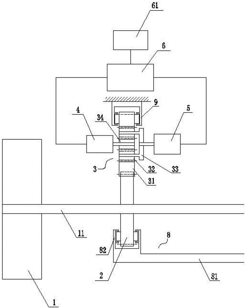
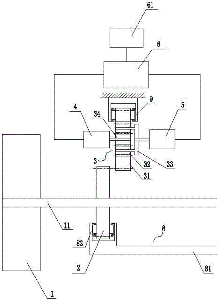
[0026] refer to figure 1 and figure 2 . An electromagnetic braking system is composed of a reduction gear 2, a planetary gear train 3, a generator 4, a motor 5, a controller 6, a brake clutch 8 and a battery pack 61, and the reduction gear 2 is connected to a wheel 1 through an axle 11. Connected, the reduction gear 2 rotates under the drive of the wheel.

[0027] The brake clutch 8 can push the reduction gear 2 to move along the axial direction of the axle 11 . The brake clutch 8 includes a push rod 81 and a first roller limiting device 82, the rollers of the first roller limiting device 82 are in contact with the side of the reduction gear 2 and can move along the reduction gear. 2 side scrolling. The push rod 81 provides a thrust for pushing the reduction gear 2 to move along the axial direction of the axle 11, and the first roller limiting device 82 plays the role of transmitting the thrust to the reduction gear 2 and limiting .

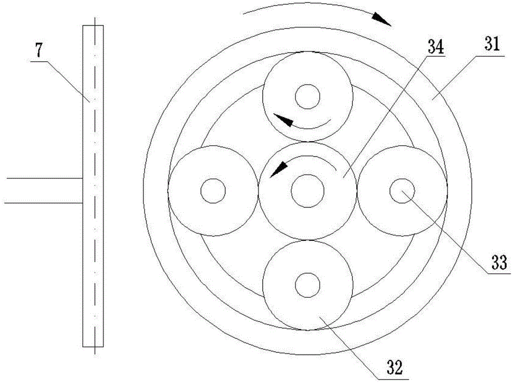
[0028] The planetary gear train 3 i...


PUM


Abstract

The invention relates to an electromagnetic braking system which comprises a reduction gear, a planetary gear train, a generator, a motor, a controller and a storage battery pack. The reduction gear is connected with vehicle wheels through a vehicle shaft. The reduction gear can move in the axial direction of the vehicle shaft under the driving of a brake coupling to control the mesh or separation of the reduction gear and the planetary gear train. One end of the planetary gear train is connected with the generator, and the other end of the planetary gear train is connected with the motor. The controller is respectively and electrically connected with the generator, the motor and the storage battery pack, the controller controls the generator to recycle energy consumed in a braking process and store the energy in the storage battery pack, and controls the motor to provide extra braking torque for the vehicle wheels. According to the electromagnetic braking system, an electromagnetic torque mode is used for providing the braking torque needed in the braking process, the problem of part abrasion caused by friction is avoided, braking performance is improved, and meanwhile the energy consumed in vehicle braking process can be recycled, and the energy utilization rate is improved.

Description

technical field [0001] The invention belongs to the application field of vehicle braking, and in particular relates to an electromagnetic braking system. Background technique [0002] Most of the existing vehicle braking systems use hydraulic braking systems, and the hydraulic braking systems use brake pads and brake discs to squeeze and generate sliding friction to achieve vehicle braking, that is, braking. The sliding friction between the brake pad and the brake disc will cause the contact surface of the brake pad and the brake disc to wear, resulting in shortened working life of the parts, and the parts need to be replaced when a certain degree of wear is reached. Moreover, the braking performance of the vehicle braking system will also decrease due to the wear and tear of components. [0003] During the friction between the brake pad and the brake disc, a large amount of heat energy will be generated. If the heat cannot be dissipated in time, the braking performance wil...

Claims


Application Information

Patent Timeline
Patent Type & Authority Patents(China)
IPC IPC(8): B60L7/20
Inventor 郑杰青黄悦伟仇亿
Owner ZHEJIANG UNIV
Learn More