Check patentability & draft patents in minutes with Patsnap Eureka AI!

A conjoined multifunctional hydraulic movable dam system

A movable dam and multi-functional technology, applied in sea area engineering, construction, barrage/weir, etc., can solve the problems of poor sealing of the rotating mechanism, cumbersome construction, and reduce the number of times of installation and construction of the movable dam, so as to reduce the number of construction times and simplify the construction , the effect of expanding the scope of application

Active Publication Date: 2021-08-20
ANHUI MINGCHUAN ACTIVITIES DAM TECH CO LTD
View PDF6 Cites 0 Cited by
  • Summary
  • Abstract
  • Description
  • Claims
  • Application Information

AI Technical Summary

Problems solved by technology

[0010] Aiming at the deficiencies of the prior art, the present invention provides a conjoined multifunctional hydraulic movable dam system, which solves the problem that the installation and arrangement of the existing hydraulic movable dam is relatively cumbersome and requires construction personnel to repeatedly lift a single movable dam The units are installed multiple times, and it is impossible to design the movable dam into a large component of the movable dam by multi-unit conjoined design to reduce the number of installations of the movable dam. The rotating mechanism at the bottom of the existing movable dam is poorly sealed, and the existing hydraulic activities The dam surface and the movable connection between the hydraulic cylinder and the movable connection between the hydraulic cylinder and the ground base are prone to corrosion

Method used


Image

  • A conjoined multifunctional hydraulic movable dam system
  • A conjoined multifunctional hydraulic movable dam system
  • A conjoined multifunctional hydraulic movable dam system

Examples


Embodiment Construction

[0040] The following will clearly and completely describe the technical solutions in the embodiments of the present invention with reference to the accompanying drawings in the embodiments of the present invention. Obviously, the described embodiments are only some, not all, embodiments of the present invention. Based on the embodiments of the present invention, all other embodiments obtained by persons of ordinary skill in the art without making creative efforts belong to the protection scope of the present invention.

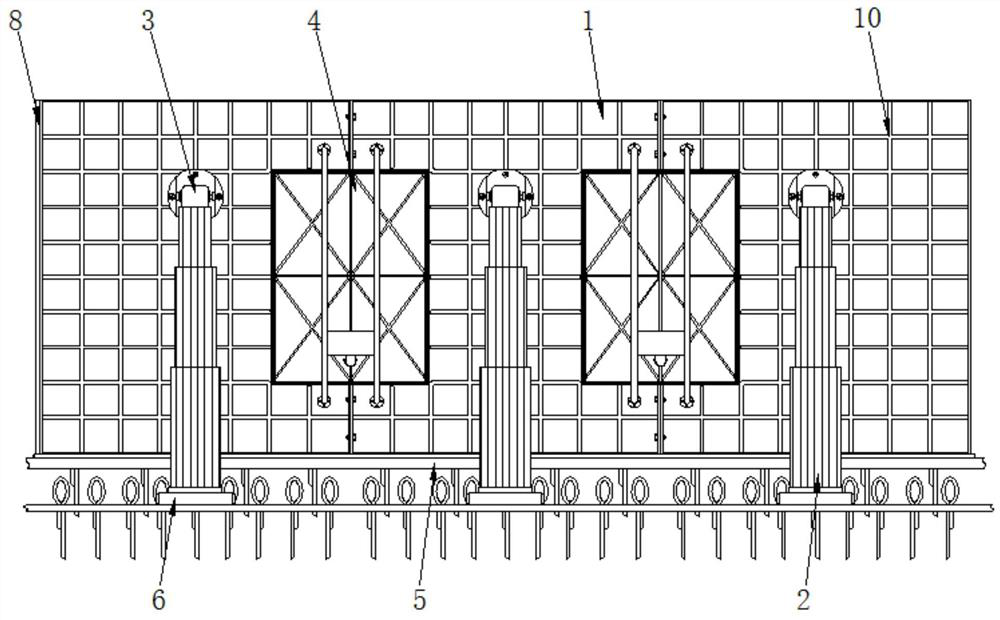
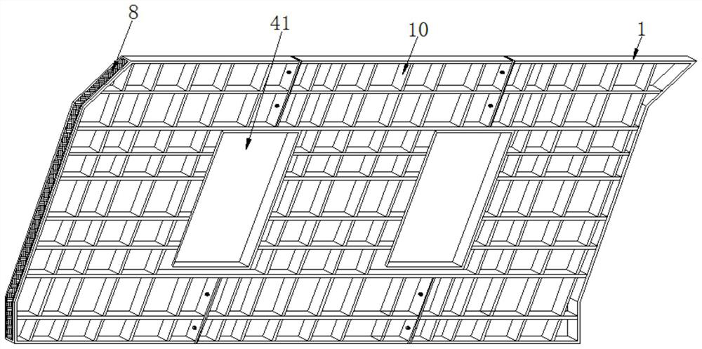
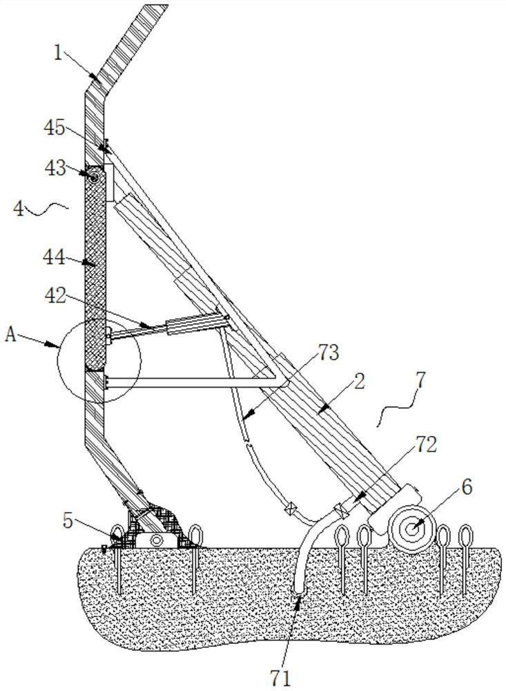
[0041] see Figure 1-11 , the embodiment of the present invention provides a technical solution: a conjoined multifunctional hydraulic movable dam system, including three groups of movable dam units, and each movable dam unit is composed of a movable dam plate 1 and a hydraulic cylinder 2, and the hydraulic cylinder The second is to use a large-bore oil cylinder with a model number of MG125-370-M6828. The back of the movable dam 1 and the top of the hydraulic ...


PUM


Abstract

The invention discloses a conjoined multifunctional hydraulic movable dam system, which includes three groups of movable dam units, and each movable dam unit is composed of a movable dam plate and a hydraulic cylinder, the back of the movable dam plate is connected with the hydraulic cylinder The top ends are rotationally connected by an upper anti-rust hinge assembly, and the movable dam plates of the two groups of movable dam units are fixedly connected by bolts, and a small displacement movable gate assembly is arranged between the movable dam plates of the two groups of movable dam units , The present invention relates to the technical field of hydraulic engineering. The conjoined multi-functional hydraulic movable dam system can quickly and safely install the movable dam on the construction site. Realize that by designing the movable dam unit as a plurality of small flood discharge outlets, the movable dam can adapt to the required flood discharge of different discharges, and the adjustable range of flood discharge methods with different discharges can be enlarged.

Description

technical field [0001] The invention relates to the technical field of water conservancy engineering, in particular to a conjoined multifunctional hydraulic movable dam system. Background technique [0002] The structure of the hydraulic movable dam is composed of an arc-shaped dam surface, a motor screw rod, a hydraulic rod, a support rod, a hydraulic cylinder, a starting power station and a hydraulic pump station, and the screw rod hydraulic cylinder is used to straighten the back of the movable dam surface with the bottom as the axis. , to achieve the purpose of raising the dam to stop water and lowering the dam to discharge the flood. The sliding support rod is used to support the back of the movable dam surface to form a stable supporting pier dam. Small hydraulic cylinders and limit cards are used to form a mutual interaction between the fixed and movable supporting pier dams. Exchange, to achieve the purpose of fixed water blocking and movable dam lowering, using buoy...

Claims


Application Information

Patent Timeline
Patent Type & Authority Patents(China)
IPC IPC(8): E02B7/20E02B7/54
CPCE02B7/20E02B7/54
Inventor 汤中旺
Owner ANHUI MINGCHUAN ACTIVITIES DAM TECH CO LTD
Features
  • R&D
  • Intellectual Property
  • Life Sciences
  • Materials
  • Tech Scout
  • Unparalleled Data Quality
  • Higher Quality Content
  • 60% Fewer Hallucinations
Learn More