Inflatable Tooth Dam

a tooth dam and inflatable technology, applied in the field of dental implants, can solve the problems of band clamps being uncomfortable, job complexity goes up, complications down the road, etc., and achieve the effect of a single use, inexpensive, tooth dam

Active Publication Date: 2022-05-05
THORESON MARK
View PDF0 Cites 1 Cited by
  • Summary
  • Abstract
  • Description
  • Claims
  • Application Information

AI Technical Summary

Benefits of technology

[0007]In accordance with various embodiments, an inexpensive, single use inflatable dental matrix (tooth dam) is provided.
[0008]In one aspect, a marix that is easy to install and remove and can closely contour to the anatomy of posterior teeth is provided.
[0009]In another aspect, a matrix that can be installed quickly and securely without the need for additional expensive equipment.
[0010]In yet another aspect, a cutable, sterile matrix that can self-seal at any inflatable profile is provided.

Problems solved by technology

Here the job complexity goes up.
First, there is no side boundary to retain the filling material and second, any filling material that does spill over between teeth, will cause complications down the road.
These band clamps are uncomfortable and often require wedges to ensure the seal around the tooth is above the gum line, or to separate the teeth enough such that the band may be placed between them.
Additionally, they can cause gum irritation.

Method used


Image

  • Inflatable Tooth Dam
  • Inflatable Tooth Dam
  • Inflatable Tooth Dam

Examples


first embodiment

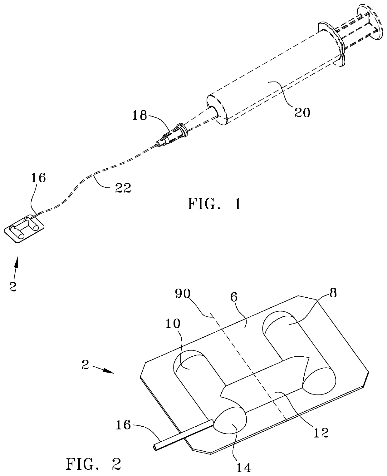
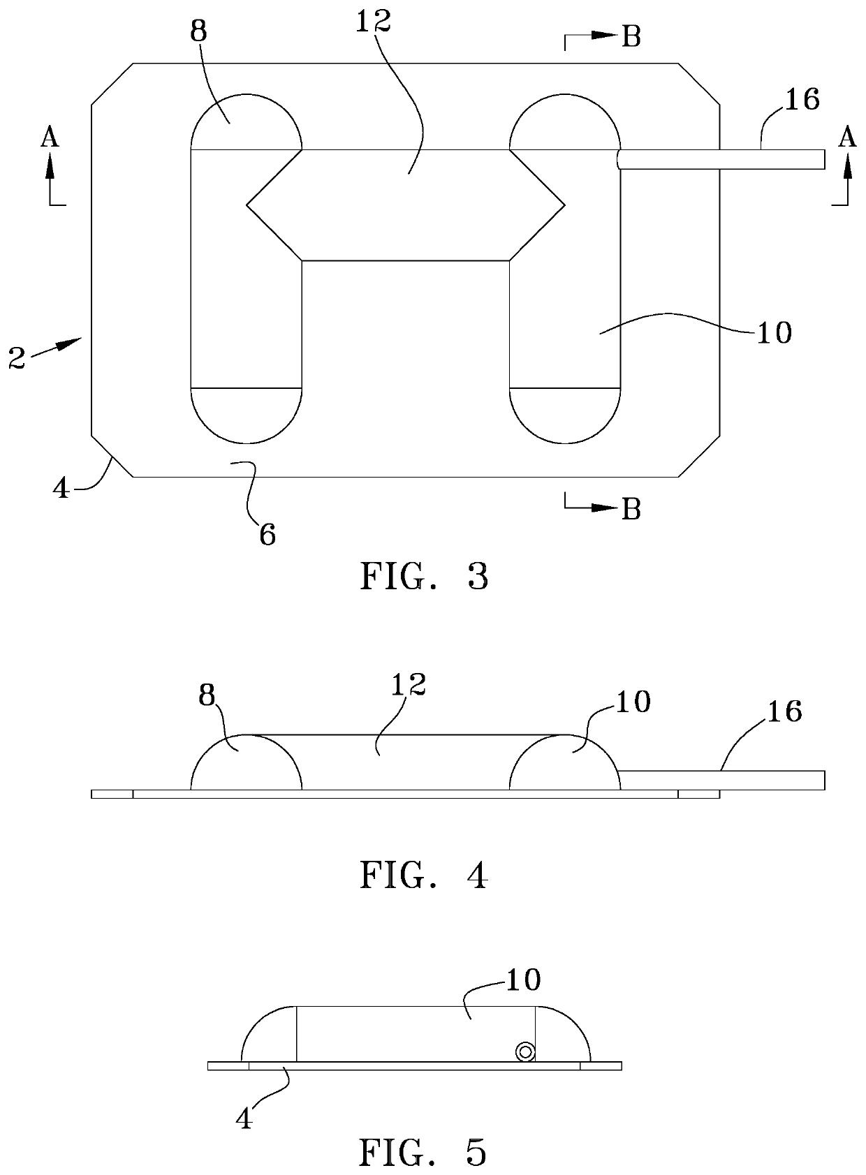
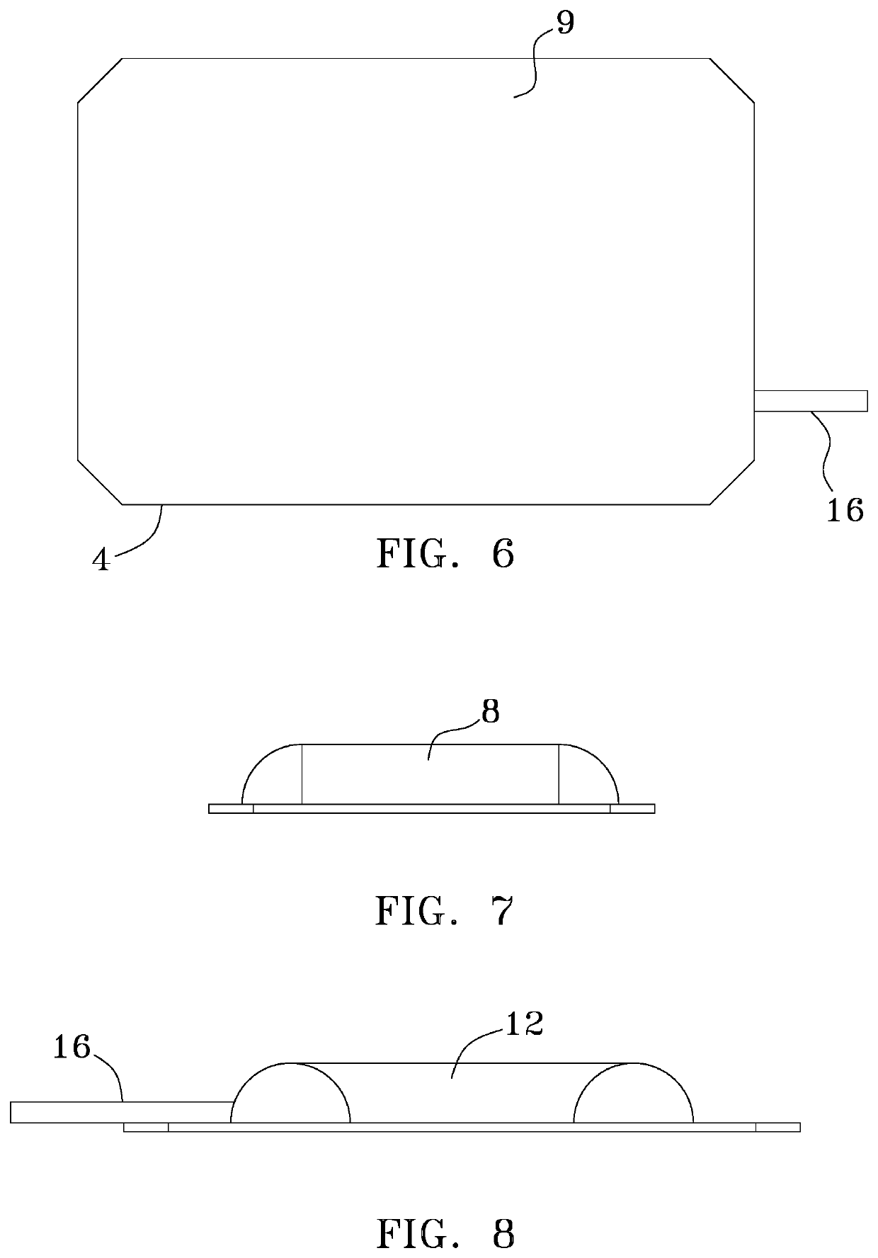
[0040]Looking at FIGS. 2 and 6 of the first embodiment matrix 2, it can be seen that the device is made of a cut-able flexible, planar panel 4 of a first thickness that has polymer film 6 of a second, thinner thickness, affixed to its panel's back face. The polymer film6 is shaped into first and second substantially similar linear air bags (linear air pockets between the panel 4 and the inner side of the polymer film 6) 8, 10 connected by an air channel 12. In the specific geometric configuration used in the preferred embodiment matrix 2, the air channel 12 is located transverse to the longitudinal arrangement of the air bags 8 and 10, intersecting them perpendicularly. While this geometric arrangement has tested well it is known that other geometric configurations of air bags 8, 10 such as square, rectangular or round will work. The height of the air bags 8, 10 is slightly larger than the height of an average human molar or premolar.

embodiment 2

[0041]Looking at FIGS. 3-10, it is illustrated that the air bags 8, 10 have ¼ spherical ends 14, again that may have other configurations depending on changes in fabrication tooling. Extending from one of the air bags (in the illustrated embodiment the second air bag 10) is an inflation conduit 16. In the preferred embodiment 2 the inflation conduit 16 extends beyond the extent or the peripheral edge of the panel 4. Looking at FIGS. 11 and 12 it can be best seen that the inflation conduit 16 extends and is sealed at the entry to the second air bag 10. (In the alternate embodiment matrix 50 (FIGS. 13 and 14) the inflation conduit 16 is replaced by an inflation channel 52 that is a linear section of the panel 4 that formed as a raised semi-circular passage that has its proximal opening at the top edge of the panel 4 and its distal opening in the tunnel 12, between the panel 4 and the polymer film 6). The inflatable height of the air bags 8, 10 and air tunnel 12 are identical. All thre...


PUM


Abstract

A disposable, inflatable, matrix (tooth dam) used to form a temporary, removeable side wall for the placement of a tooth filling material. It establishes the original dental anatomy of the tooth, and maintains the correct contact between adjacent teeth for flossing purposes and gingival health. It accomplishes this by inflating a pair of self-sealing air chambers that extend from the back face of a planar panel that they are formed on, such that these chambers contact and press against the adjacent tooth and exert enough force to elastically secure the planar panel without wedges and clamps. It prevents the tooth filling material from leaving the prepared tooth and entering the space between the teeth to enhance flossing and proper dental hygiene. This device will greatly enhance patient comfort, procedural efficiency and consistency

Description

COPYRIGHT STATEMENT[0001]A portion of the disclosure of this patent document contains material that is subject to copyright protection. The copyright owner has no objection to the facsimile reproduction by anyone of the patent document or the patent disclosure as it appears in the Patent and Trademark Office patent file or records, but otherwise reserves all copyright rights whatsoever.FIELD[0002]The present disclosure relates, in general, to dentistry, and more particularly to tooth filling technology.BACKGROUND[0003]Tooth decay is a way of life for many people. Standard dental restorations involve the removal of decay from a tooth. After the decay has been removed and the resultant hole sterilized and dried, it is a relatively straight forward process to place restorative materials and contour to recreate normal tooth anatomy.[0004]When the decay has penetrated the side of the tooth (marginal ridge) this side has to be partially removed. Here the job complexity goes up. With the s...

Claims


Application Information

Patent Timeline
Patent Type & Authority Applications(United States)
IPC IPC(8): A61C5/82
CPCA61C5/82A61C2201/00A61C5/88
Inventor THORESON, MARK
Owner THORESON MARK
Why Eureka
Try Eureka