
Municipal pipeline dredging device with adjustable working diameter and implementation method

A technology of municipal pipelines and working diameters, applied in water supply devices, cleaning sewer pipes, waterway systems, etc., can solve problems such as inconvenient storage, inability to fold and adjust mobile devices, scraping and breaking of roller brackets, etc., and achieve the effect of convenient adjustment

Inactive Publication Date: 2020-12-04
刘亚明
View PDF20 Cites 0 Cited by
  • Summary
  • Abstract
  • Description
  • Claims
  • Application Information

AI Technical Summary

Problems solved by technology

[0002] As an important project in urban construction, municipal pipelines involve a wide range of areas, mainly involving the laying of various urban pipelines. There are many types of these pipelines. After the laying is completed, regular maintenance and maintenance are required to ensure their normal production and operation. Among them, it is essential to clean these pipelines. Long-term use leads to a large amount of sludge accumulated inside. The hidden dangers of these sludges are huge, which will not only cause pipeline blockage, but also seriously pollute the water.
[0003] However, the dredging head of the current municipal pipeline dredging device is a fixed structure. When the dredging head is working and after the work is over, the mobile device cannot be folded and adjusted, resulting in the phenomenon that the roller bracket is prone to scratching and breaking, and it is inconvenient to store.

Method used


Image

  • Municipal pipeline dredging device with adjustable working diameter and implementation method
  • Municipal pipeline dredging device with adjustable working diameter and implementation method
  • Municipal pipeline dredging device with adjustable working diameter and implementation method

Examples


Embodiment 1

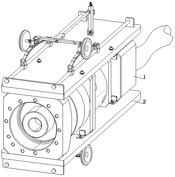
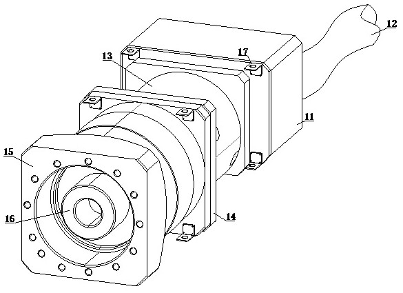
[0037] see Figure 1-2, a dredging device for municipal pipelines with adjustable working diameter, comprising a dredging head 1 and a moving device 2, the outer upper and lower ends of the dredging head 1 are equipped with a moving device 2, and the dredging head 1 includes a chassis 11, a connecting pipe 12 , water pipe 13, connecting piece 14, water spray head 15, water spray hole 16 and right-angle piece 17, one end side of cabinet 11 is equipped with connecting pipe 12, and the other end of cabinet 11 is equipped with water pipe 13, and the other end of water pipe 13 One end is equipped with a connecting piece 14, the other end of the connecting piece 14 is equipped with a water spray head 15, the other end side of the water spray head 15 is provided with a water spray hole 16, the outer surface of the cabinet 11 is equipped with a right-angle piece 17, the right-angle piece 17 The upper end is equipped with mobile device 2.

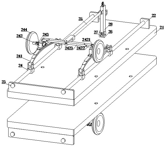
[0038] see Figure 3-4 , the moving device ...

Embodiment approach

[0040] The present invention provides another technical solution: a method for implementing a municipal pipeline dredging device with adjustable working diameter, comprising the following steps:

[0041] S01: Place the dredging head 1 and the mobile device 2 on the ground and make connections;

[0042] S02: Pull the handle 284 upwards according to the diameter of the municipal pipeline, so that the limit rod 28422 can fall off from the limit hole 271 at the lowermost end of the angle plate 27;

[0043] S03: pull the handle 284 backward at this time, the handle 284 can drive the support assembly 28 to rotate on the outer surface of the angle plate 27, and the lower end of the support assembly 28 is in the process of rotation, and one end of the connecting rod 25 is pulled by the support assembly 28 , while the connecting rod 25 pulls the second rotating rod 2423, the second rotating rod 2423 pushes the first connecting head 2421 outward, and the first connecting head 2421 makes...

Embodiment 2

[0046] see Figure 1-2 , a dredging device for municipal pipelines with adjustable working diameter, comprising a dredging head 1 and a moving device 2, the outer upper and lower ends of the dredging head 1 are equipped with a moving device 2, and the dredging head 1 includes a chassis 11, a connecting pipe 12 , water pipe 13, connecting piece 14, water spray head 15, water spray hole 16 and right-angle piece 17, one end side of cabinet 11 is equipped with connecting pipe 12, and the other end of cabinet 11 is equipped with water pipe 13, and the other end of water pipe 13 One end is equipped with a connecting piece 14, the other end of the connecting piece 14 is equipped with a water spray head 15, the other end side of the water spray head 15 is provided with a water spray hole 16, the outer surface of the cabinet 11 is equipped with a right-angle piece 17, the right-angle piece 17 The upper end is equipped with mobile device 2.

[0047] see Figure 3-4 , the moving device...


PUM


Abstract

The invention discloses a municipal pipeline dredging device with an adjustable working diameter. The device comprises a dredging head and moving devices, the upper end and the lower end of the outersurface of the dredging head are provided with the moving devices, handles are pushed upwards to enable the handles to move upwards, and after the handles move upwards, the handles are pulled backwards to enable the handles to drive supporting rods to rotate at the two ends of an angle plate. Therefore, the moving devices can be unfolded, the supporting rods are rotated reversely,a moving assemblyand the supporting rods are folded and adjusted, and the moving assembly is effectively protected. The invention further discloses an implementation method of the municipal pipeline desilting devicewith the adjustable working diameter, when the angle of the supporting rods and the moving assembly needs to be adjusted, the handles are pushed forwards while the handles are pulled upwards, and after the supporting rods rotate to a proper angle, the handles are loosened, limiting rods can be clamped into limiting holes under the reverse thrust of the same magnetism of a first magnetic block anda second magnetic block, and the moving assembly can be adjusted and fixed.

Description

technical field [0001] The invention relates to the technical field of municipal pipeline desilting equipment, in particular to a municipal pipeline desilting device with adjustable working diameter and an implementation method. Background technique [0002] As an important project in urban construction, municipal pipelines involve a wide range of areas, mainly involving the laying of various urban pipelines. There are many types of these pipelines. After the laying is completed, regular maintenance and maintenance are required to ensure their normal production and operation. , Among them, it is essential to clean these pipelines. Long-term use leads to a large amount of sludge accumulated inside. These sludges have huge hidden dangers, which will not only cause pipeline blockage, but also seriously pollute water. [0003] However, the dredging head of the current municipal pipeline dredging device is of a fixed structure. When the dredging head is working and after the work...

Claims


Application Information

Patent Timeline
Patent Type & Authority Applications(China)
IPC IPC(8): E03F9/00
CPCE03F9/007
Inventor 丁西焘
Owner 刘亚明
Learn More