Al technical title is built by PatSnap Al team. It summarizes the technical point description of the patent document.
A technology of electric actuators and rotating tables, which is applied in the direction of electric components, electrical components, electromechanical devices, etc., can solve the problems that the installation requirements cannot be met, and the installation angle of the electric actuator cannot be adjusted flexibly, so as to achieve the effect of accurate adjustment
Inactive Publication Date: 2020-12-04
陈永志
View PDF11 Cites 2 Cited by
Summary
Abstract
Description
Claims
Application Information
AI Technical Summary
This helps you quickly interpret patents by identifying the three key elements:
Problems solved by technology
Method used
Benefits of technology
Problems solved by technology
[0003] When using an electric actuator, it needs to be installed on a component first. The installation requirement of the existing electric actuator is not just to install it at a conventional angle with the component, but to adjust the electric actuator according to the use requirements installation angle to ensure that the electric actuator can be used to achieve the corresponding purpose. However, the existing electric actuator cannot flexibly adjust the installation angle and cannot meet the installation requirements.
Method used
Image
Click on the blue label to locate the original text in one second.
Reading with bidirectional positioning of images and text.
Examples
Embodiment Construction
[0026] In order to make the object, technical solution and advantages of the present invention clearer, the present invention will be further described in detail below in combination with specific embodiments and with reference to the accompanying drawings. It should be understood that these descriptions are exemplary only, and are not intended to limit the scope of the present invention. Also, in the following description, descriptions of well-known structures and techniques are omitted to avoid unnecessarily obscuring the concept of the present invention.
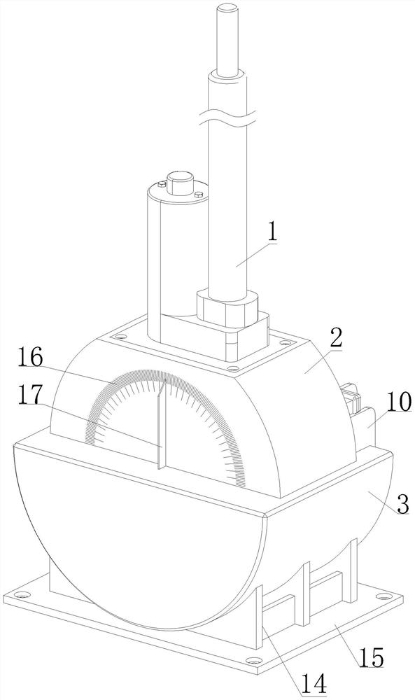
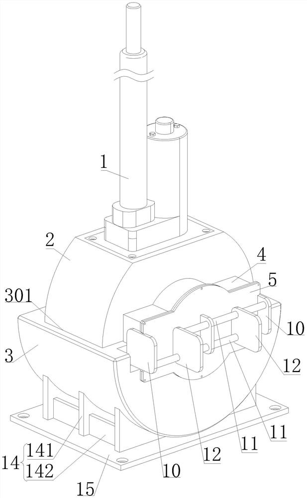
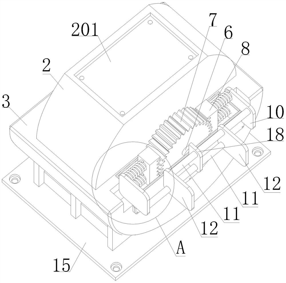
[0027] Such as Figure 1-5 As shown, an electric actuator mechanism proposed by the present invention includes an elastic limit assembly 100, an electric actuator body 1, a rotating table 2, a mounting table 3, a mounting cover 4, a cover body 5, a connecting shaft 6, a gear 7 and mounting plate 15;
[0028] The electric actuator body 1 is connected with the turntable 2; the turntable 2 is rotated and set on the install...
PUM
Abstract
The invention discloses an electric actuator mechanism. The electric actuator mechanism comprises an elastic limiting assembly, an electric actuator body, a rotating table, an installing table, an installing cover, a cover body, a connecting shaft, a gear and an installing plate, the electric actuator body is connected with the rotating table, the rotating table is rotationally arranged on the installing table, the mounting table is arranged on the installing plate, the installing cover and the cover body are both connected with the installing table, the installing cover is connected with thecover body, the connecting shaft is connected with the rotating table and is rotationally arranged on the installing cover, the gear is arranged on the connecting shaft, the elastic limiting assemblycomprises a rack, a sliding rod, a connecting plate, a connecting rod, a pressing plate and an elastic piece, the rack is clamped with the gear, the two ends of the sliding rod are respectively connected with the rack and the connecting plate and slidably arranged on the installing cover, the two ends of the connecting rod are respectively connected with the connecting plate and the pressing plate, and the two ends of the elastic piece are respectively connected with the inner surface of the installing cover and the rack. According to the electric actuator mechanism, the installing angle can be flexibly adjusted, the angle is determined, and it is guaranteed that the driving effect can be achieved at the determined angle.
Description
technical field [0001] The invention relates to the technical field of electric actuators, in particular to an electric actuator mechanism. Background technique [0002] The broadest definition of an electric actuator mechanism is a drive that provides linear or rotary motion, using some kind of drive energy and operating under the action of some kind of control signal. Actuator mechanisms use fluid, gas, electricity, or other energy sources and convert them into drive action through motors, cylinders, or other devices. There are three basic types of electric actuator mechanisms: partial rotary, multi-rotary and linear drive. [0003] When using an electric actuator, it needs to be installed on a component first. The installation requirement of the existing electric actuator is not just to install it at a conventional angle with the component, but to adjust the electric actuator according to the use requirements To ensure that the electric actuator can be used to achieve t...
Claims
Application Information
Patent Timeline
Application Date:The date an application was filed.
Publication Date:The date a patent or application was officially published.
First Publication Date:The earliest publication date of a patent with the same application number.
Issue Date:Publication date of the patent grant document.
PCT Entry Date:The Entry date of PCT National Phase.
Estimated Expiry Date:The statutory expiry date of a patent right according to the Patent Law, and it is the longest term of protection that the patent right can achieve without the termination of the patent right due to other reasons(Term extension factor has been taken into account ).
Invalid Date:Actual expiry date is based on effective date or publication date of legal transaction data of invalid patent.