Exterior wall decoration type universal cable trough

A decorative type, cable trough technology, applied in the direction of electrical components, etc., can solve the problems of unsightly vision, affecting urban beautification, inconvenient maintenance, etc., to facilitate construction and future maintenance of lines, shorten the installation and wiring period, and excellent water resistance Effect

Inactive Publication Date: 2020-12-04
贾思宇
View PDF6 Cites 1 Cited by
  • Summary
  • Abstract
  • Description
  • Claims
  • Application Information

AI Technical Summary

Problems solved by technology

[0005] In order to solve the problems that the existing external wall cables are exposed and hung, it is not easy to maintain, and at the same time, it is visually unattractive and affects the beautification of the city, and further proposes an external wall decoration type universal cable trough

Method used


Image

  • Exterior wall decoration type universal cable trough
  • Exterior wall decoration type universal cable trough
  • Exterior wall decoration type universal cable trough

Examples


specific Embodiment approach 1

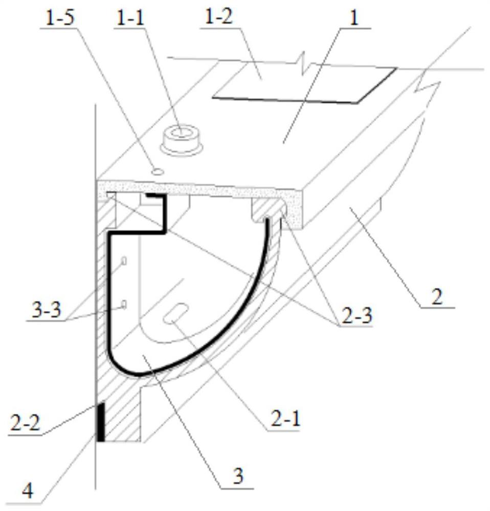
[0020] Specific implementation mode one: combine Figure 1 to Figure 8 Explanation, the exterior wall decoration type universal cable trough described in this embodiment includes a type trough, the type trough includes an upper cover 1 and a trough body 2, the inner wall of the trough body 2 is a plane, and the outer wall of the trough body 2 is an arc surface , the lower end of the inner side wall of the tank body 2 and the lower end of the outer side wall are connected through a smooth curved surface, the inner side walls of the two ends of the tank body 2 are fixedly connected with metal connectors 3 , and the upper end of the tank body 2 is provided with a loam cake 1 .

[0021] The overall shape of the groove matches the architectural style. In this embodiment, the metal connector 3 is used to fix the groove body 2 on the outer wall, the inner wall of the groove body 2 is close to the outer wall, and the outer wall of the groove body 2 has an arc curve Transition, the upp...

specific Embodiment approach 2

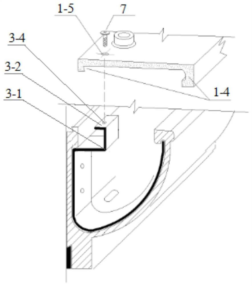
[0023] Specific implementation mode two: combination Figure 1 to Figure 8 It is explained that the upper cover 1 and the notch of the tank body 2 in this embodiment are clamped and connected. Other compositions and connection methods are the same as those in the first embodiment.

[0024] In this embodiment, the outer sides of the notches on both sides of the tank body 2 are provided with bayonet sockets 2-3, and both sides of the lower end surface of the upper cover 1 are provided with card slots, and the card slots are mounted on the outside of the bayonet sockets. The mouth width is slightly smaller than the width of the bayonet of the tank body 2, and the elasticity of the U-shaped structure of the tank body 2 is used for clamping and fixing.

specific Embodiment approach 3

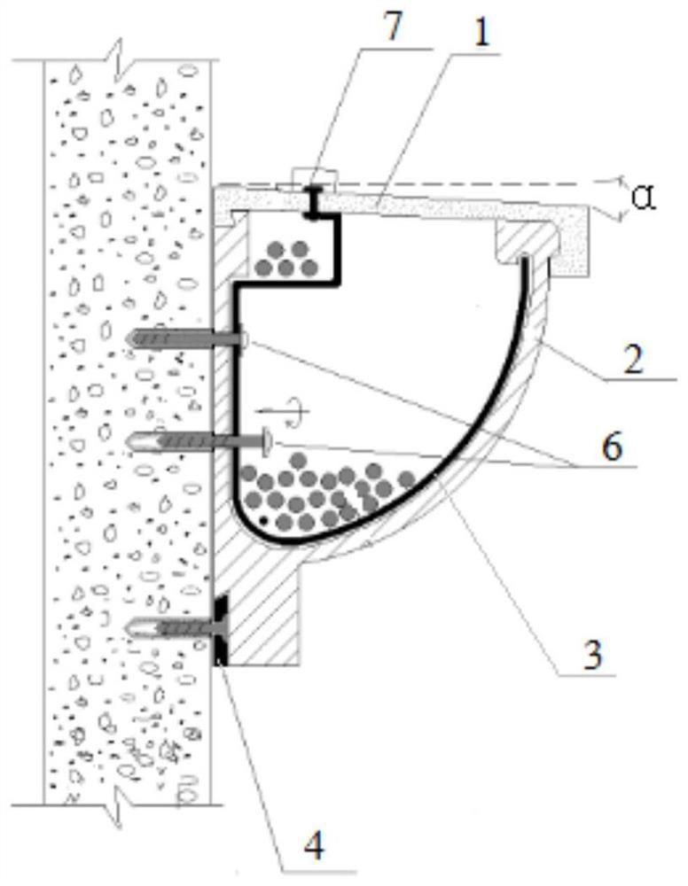
[0025] Specific implementation mode three: combination Figure 1 to Figure 8 To illustrate, the upper end surface of the upper cover 1 in this embodiment is inclined downward from the inside to the outside. Other compositions and connection modes are the same as those in Embodiment 1 or 2.

[0026] In this embodiment, the inclination angle of the upper cover 1 is α, and α is 3° to 5°, which is designed to facilitate drainage of rainwater and melting ice.


PUM


Abstract

The invention discloses an exterior wall decoration type universal cable trough, relates to the technical field of constructional engineering, and aims to solve the problems that an existing outer wall cable is exposed and externally hung, maintenance is inconvenient, meanwhile, visual attractiveness is not achieved, and urban beautification is affected.The exterior wall decoration type universalcable trough comprises a profiled groove, wherein the profiled groove comprises an upper cover and a groove body, the inner side wall of the groove body is a plane, the outer side wall of the groove body is an arc curved surface, the lower end of the inner side wall of the groove body and the lower end of the outer side wall are in transition connection through a smooth curved surface, metal connecting pieces are fixedly connected to the inner side groove walls of the two ends of the groove body, and the upper cover. The device is used for placing the cable exposed out of the building.

Description

technical field [0001] The invention relates to the technical field of construction engineering, in particular to an external wall decoration type universal cable groove. Background technique [0002] At present, the external wall wiring of cities, especially old buildings, is almost all in the form of exposed plug-ins. Although the cost is low, the disorder seriously affects the beauty of the street and the building itself. Maintenance is troublesome, and the old lines cannot be removed. Adding new lines can only be repeated on this basis disorganized. This kind of cable plug-in form is a stubborn disease of old house renovation and urban beautification. [0003] The General Office of the State Council promulgated "Several Opinions on Promoting Housing Industrialization and Improving Housing Quality" in 1999. On January 1, 2013, in the form of 2013 No. 1 document, the National Development and Reform Commission and the Ministry of Housing and Urban-Rural Development "Green ...

Claims


Application Information

Patent Timeline
Patent Type & Authority Applications(China)
IPC IPC(8): H02G3/04H02G3/30H02G3/34
CPCH02G3/0406H02G3/0418H02G3/0431H02G3/0437H02G3/30H02G3/34
Inventor 贾思宇周传喜陈尚政刘潇阳
Owner 贾思宇
Why Eureka
Try Eureka