Fire safety facility intelligent monitoring system and method

A technology of intelligent monitoring system and safety facilities, applied in the direction of electric transmission signal system, fire rescue, electric fire alarm, etc., can solve the problems of untimely follow-up, many tasks of security personnel, and difficult guarantee, etc., to achieve Compensate for sluggish response and improve fire extinguishing efficiency

Inactive Publication Date: 2020-12-08
NANJING YUEYING TECH CO LTD
View PDF4 Cites 1 Cited by
  • Summary
  • Abstract
  • Description
  • Claims
  • Application Information

AI Technical Summary

Problems solved by technology

In the existing technology, some enterprises use manual supervision by security personnel. This will cause security personnel to have many tasks, difficult to supervise the implementation, difficult to control the progress, inaccurate statistics of results, and prone to information omissions, errors, or failure to follow up in time. It has a relatively high risk, once a safety accident is triggered, it will cause economic and human losses
[0003] In addition, the management and maintenance of daily fire-fighting equipment in cities mainly rely on manual inspection and management. For fire-fighting forces with a relatively limited staffing, it is difficult to guarantee, and it is also difficult to achieve real-time performance, especially when implementing large-scale fire-fighting and rescue tasks. , fire equipment management personnel are required to complete the scheduling and guarantee of equipment warehouses and fire equipment resources in the jurisdiction within a few hours, which is extremely prone to omissions, and it is difficult to provide reliable guarantees for fire rescue support work

Method used


Image

  • Fire safety facility intelligent monitoring system and method
  • Fire safety facility intelligent monitoring system and method

Examples


Embodiment Construction

[0026] It is easy to understand that, according to the technical solution of the present invention, those skilled in the art can propose multiple structural modes and implementation modes that can be replaced without changing the essence and spirit of the present invention. Therefore, the following specific embodiments and drawings are only exemplary descriptions of the technical solution of the present invention, and should not be regarded as the entirety of the present invention or as a limitation or restriction on the technical solution of the present invention.

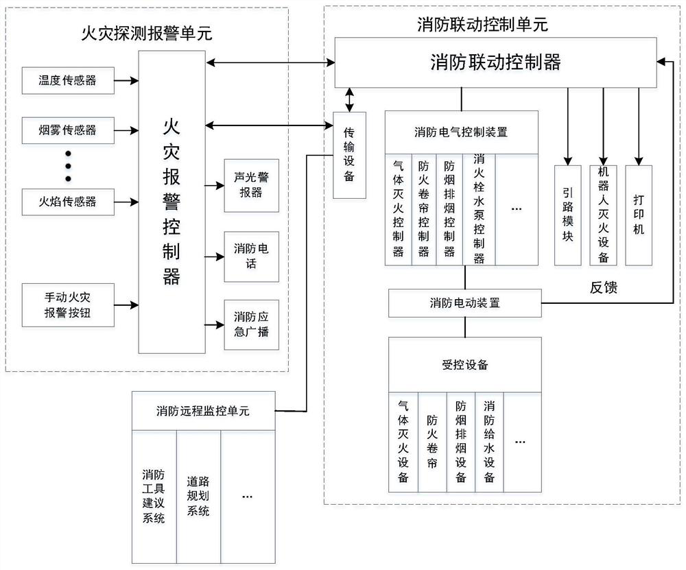
[0027] According to an embodiment of the present invention combined with figure 1 show. An intelligent monitoring system for fire safety facilities, comprising a fire detection and alarm unit, a fire linkage control unit and a fire remote monitoring unit, the fire detection and alarm unit is connected with the fire linkage control unit, and is used to send the fire alarm signal collected by the fire detection and ...


PUM


Abstract

The invention provides a fire safety facility intelligent monitoring system and method. The monitoring system comprises a fire detection alarm unit, a fire-fighting linkage control unit, and a fire-fighting remote monitoring unit, and the fire detection alarm unit is connected with the fire-fighting linkage control unit, and used for sending a fire alarm signal acquired by the fire detection alarmunit to the fire-fighting linkage control unit. The fire-fighting linkage control unit comprises a fire-fighting linkage controller, a fire-fighting electric control device, a fire-fighting electricdevice and controlled equipment which are connected in sequence, the fire-fighting linkage controller sends an electric control signal to the fire-fighting electric control device, and the fire-fighting electric control device controls the controlled equipment to act through the fire-fighting electric device. The fire-fighting remote monitoring unit is connected with the fire detection alarm unitand the fire-fighting linkage control unit through transmission equipment and is used for receiving the fire alarm signal and an equipment action signal. The operation condition of a fire safety facility can be automatically inspected, hidden dangers are eliminated, and the supervision efficiency and strength of the fire safety facility are greatly improved.

Description

technical field [0001] The invention relates to the field of fire monitoring, in particular to an intelligent monitoring system and method for fire safety facilities. Background technique [0002] In the production process of enterprises, there are many types and quantities of equipment such as security, fire protection, and production, which are extremely difficult to supervise. In the existing technology, some enterprises use manual supervision by security personnel. This will cause security personnel to have many tasks, difficult to supervise the implementation, difficult to control the progress, inaccurate statistics of results, and prone to information omissions, errors, or failure to follow up in time. It has a relatively high risk. Once a safety accident is triggered, it will cause economic and personnel losses. [0003] In addition, the management and maintenance of daily fire-fighting equipment in cities mainly rely on manual inspection and management. For fire-fig...

Claims


Application Information

Patent Timeline
Patent Type & Authority Applications(China)
IPC IPC(8): A62C37/00G08B17/06G08B17/10G08B7/06
CPCA62C37/00G08B17/06G08B17/10G08B7/06
Inventor 许舟赵静
Owner NANJING YUEYING TECH CO LTD
Why Eureka
Try Eureka