
Automatic metal pipe bending device for mechanical equipment machining

A technology of mechanical equipment and bending device, which is applied in the direction of feeding device, positioning device, storage device, etc., can solve the problems of bending degree limited by working height and low bending efficiency, and achieve improved bending efficiency, simple and reasonable structure, Quick and easy effects to use

Inactive Publication Date: 2020-12-08
刘素勤
View PDF0 Cites 1 Cited by
  • Summary
  • Abstract
  • Description
  • Claims
  • Application Information

AI Technical Summary

Problems solved by technology

[0003] Components commonly used in metal pipe fittings construction sites and various mechanical engineering, in the actual use process, metal pipes will be processed to different degrees according to different conditions, such as cutting, polishing, bending and other processes, and the bending process is inseparable. The use of open bending equipment, as the name suggests, is to bend the original metal pipe in a certain degree of arc shape. The traditional bending is to support the two ends of the metal pipe, and then to the middle of the middle from top to bottom. Force is applied downwards to achieve the purpose of bending. The bending efficiency of this kind of bending equipment that applies force only from the middle is very low, and the bending degree is limited by the working height, so it needs to be solved urgently.

Method used

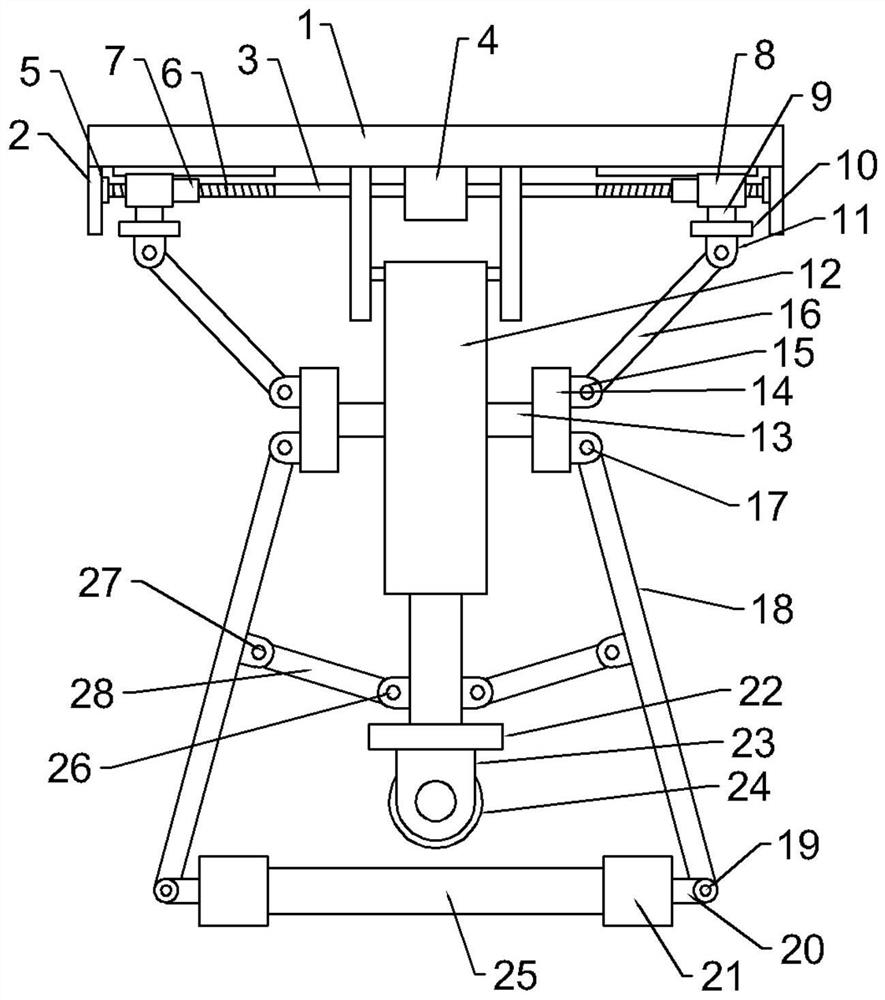

Image

  • Automatic metal pipe bending device for mechanical equipment machining
  • Automatic metal pipe bending device for mechanical equipment machining
  • Automatic metal pipe bending device for mechanical equipment machining

Examples


Embodiment Construction

[0025] Below, in conjunction with accompanying drawing and specific embodiment, the invention is further described:

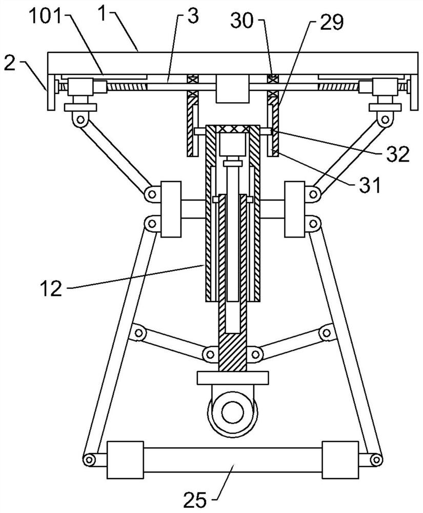
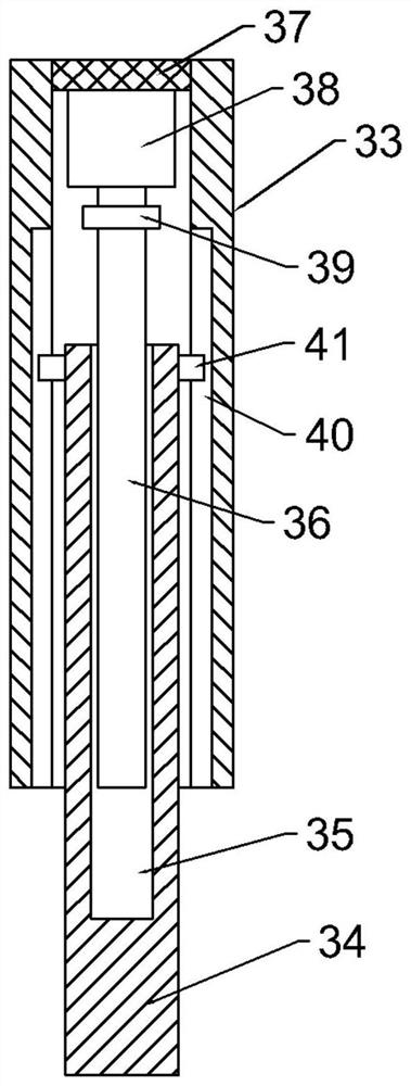
[0026] see Figure 1-5According to an embodiment of the present invention, an automatic bending device for metal pipes for mechanical equipment processing includes a fixed plate 1, and fixed blocks 2 are fixedly installed on the bottom of the fixed plate 1 along the two ends of its length direction, two An adjustment shaft 3 is arranged between the fixed blocks 2, a power box 4 is installed in the middle of the adjustment shaft 3, and the power box 4 is fixedly installed on the bottom center of the fixed plate 1, and the two ends of the adjustment shaft 3 are provided with threaded parts 6. The thread direction on the threaded part 6 at both ends is oppositely set, and the screw sleeve 7 is installed on the threaded part 6. The end of the screw sleeve 7 away from the center of the adjustment shaft 3 is fixedly linked with a moving sleeve 8, and the bottom of th...


PUM


Abstract

The invention discloses an automatic metal pipe bending device for mechanical equipment machining. The device comprises a fixed plate, fixed blocks, an adjusting shaft and a power box, wherein threaded portions are arranged at the ends of the adjusting shaft, the thread directions of the threaded portions at the two ends are opposite, threaded sleeves are mounted on the threaded portions, a movable sleeve is fixedly connected to the end, away from the center of the adjusting shaft, of each threaded sleeve, a connecting block is fixedly mounted at the bottom of the outer side wall of each movable sleeve, and a connecting plate is fixedly mounted at the bottom end of each connecting block. The device has the advantages that the working height can be adjusted, the position of a pressing wheelcan be adjusted, and force application of the pressing wheel to a metal pipe is realized, so that the effect of bending the metal pipe is achieved; and pipe head clamps at the bottom ends of two swing rods can get close to each other, certain extrusion force can be obtained, the bending efficiency of the metal pipe is improved, and the metal pipe can be prevented from being separated from a sleeve.

Description

technical field [0001] The invention relates to the field of mechanical equipment processing, in particular to an automatic metal pipe bending device for mechanical equipment processing. Background technique [0002] There are many kinds of mechanical equipment. When the mechanical equipment is running, some of its parts and even itself can perform different forms of mechanical movement. Mechanical equipment consists of driving device, transmission device, transmission device, working device, braking device, protection device, lubrication system, cooling system and other parts. [0003] Components commonly used in metal pipe fittings construction sites and various mechanical engineering, in the actual use process, metal pipes will be processed to different degrees according to different conditions, such as cutting, polishing, bending and other processes, and the bending process is inseparable. The use of open bending equipment, as the name suggests, is to bend the original ...

Claims


Application Information

Patent Timeline
IPC IPC(8): B21D7/06B21D7/16B21D43/00
CPCB21D7/06B21D7/16B21D43/003
Inventor 刘素勤
Owner 刘素勤
Learn More