
wireless charging device

A technology for wireless charging and electronic devices, which is applied in the direction of circuit devices, battery circuit devices, current collectors, etc., and can solve the problems that wireless charging devices cannot firmly fix electronic devices

Active Publication Date: 2022-05-03
PRIMAX ELECTRONICS LTD
View PDF6 Cites 0 Cited by
  • Summary
  • Abstract
  • Description
  • Claims
  • Application Information

AI Technical Summary

Problems solved by technology

However, this wireless charging device cannot firmly fix the electronic device on it

Method used


Image

  • wireless charging device
  • wireless charging device
  • wireless charging device

Examples


Embodiment Construction

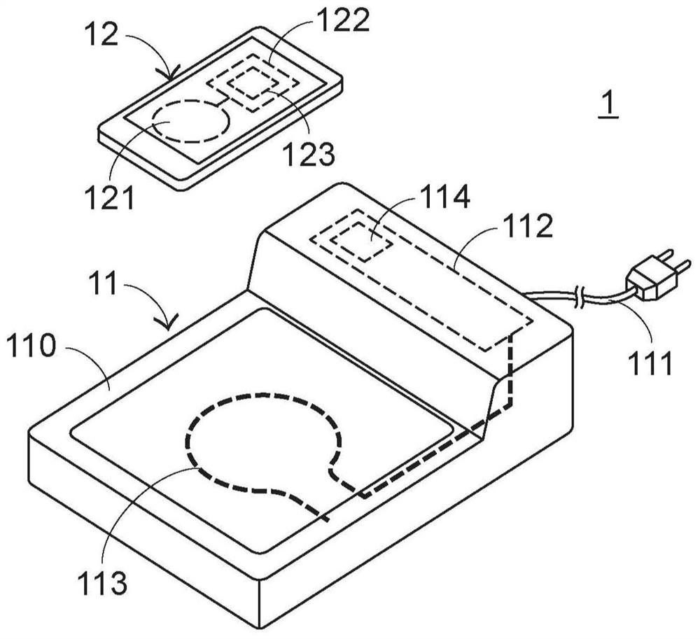
[0056] The invention provides a wireless charging device to solve the problems in the prior art. Embodiments of the present invention will be further explained in conjunction with the accompanying drawings below. In the drawings, the shape and thickness may be exaggerated for the sake of simplification and convenient labeling. It can be understood that components not particularly shown in the drawings or described in the specification are forms known to those of ordinary skill in the art. Those skilled in the art can make various changes and modifications according to the content of the present invention.

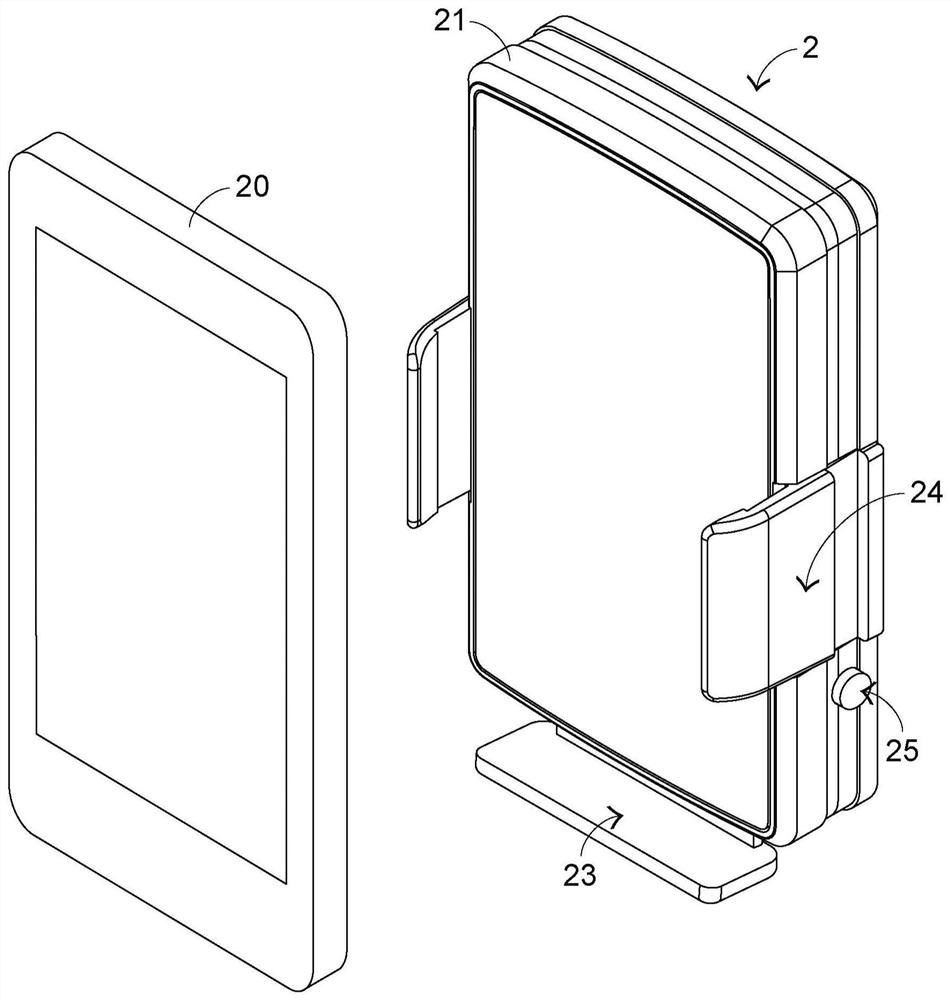
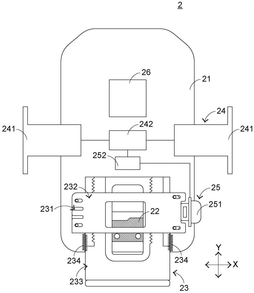
[0057] Please also see figure 2 as well as image 3 , figure 2 It is a schematic diagram of the structural appearance of the wireless charging device and the electronic device in the first preferred embodiment of the present invention, and image 3 It is a partial structural diagram of the wireless charging device in the first preferred embodiment of the present inve...


PUM


Abstract

The present invention provides a wireless charging device, which is used to carry an electronic device and wirelessly transmit a power to the electronic device. The wireless charging device includes a housing, a trigger switch capable of generating a trigger signal, a bearing seat group, a clamping mechanism and control module. The bearing seat group is arranged at one end of the casing, which can carry the electronic device, and press the trigger switch by the weight of the electronic device. The clamping mechanism is connected to the trigger switch, which can receive the trigger signal and clamp the electronic device on the supporting seat set. The control module is connected to the bearing set, and can be triggered so that the bearing set no longer touches the trigger switch, so as to stop the clamping mechanism from clamping the electronic device.

Description

technical field [0001] The present invention relates to a charging device, in particular to a wireless charging device utilizing wireless charging technology. Background technique [0002] Most of the electronic devices on the market have a thin and light appearance and are easy to carry, and the electronic devices use a touch screen, so that the electronic device can be operated by inputting instructions through the touch screen. The electronic device includes a smart phone, a tablet computer, a digital Assistant (Personal Digital Assistant, PDA) or a handheld game console (such as: PSP, NDSL and Gameboy series game consoles), etc. Due to the portable nature of the above-mentioned electronic devices, these electronic devices cannot be connected to a power source at any time and must be equipped with a battery that supplies power. to charge the battery. [0003] When the power of the electronic device is insufficient, the user uses a connection line to charge the rechargea...

Claims


Application Information

Patent Timeline
Patent Type & Authority Patents(China)
IPC IPC(8): H02J7/00H02J50/10H02J50/12
CPCH02J7/0044H02J50/10H02J50/12
Inventor 陈柏安
Owner PRIMAX ELECTRONICS LTD
Learn More