
Bending machine

A bending processing and bending technology, which is applied in the field of bending processing machines, can solve problems such as processing errors and achieve the effect of efficient bending processing operations

Active Publication Date: 2005-12-14
AMADA CO LTD
View PDF4 Cites 1 Cited by
  • Summary
  • Abstract
  • Description
  • Claims
  • Application Information

AI Technical Summary

Problems solved by technology

In the case of inaccurate positioning, no matter whether the above-mentioned small protrusion in the above-mentioned window hole (small hole) needs to be bent or not, it will be bent together to the part surrounding the above-mentioned window hole (small hole), causing processing errors

Method used


Image

  • Bending machine
  • Bending machine
  • Bending machine

Examples


Embodiment Construction

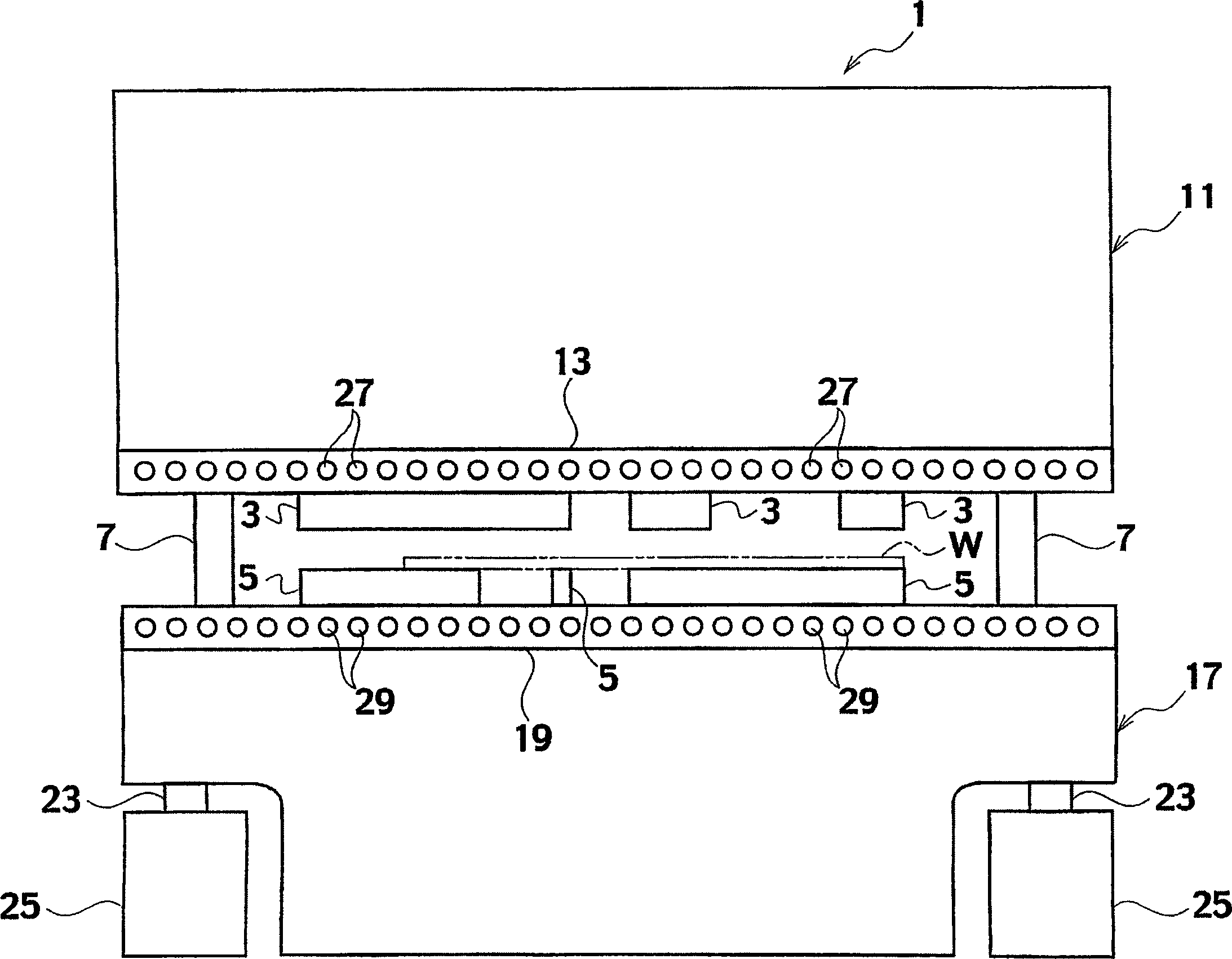
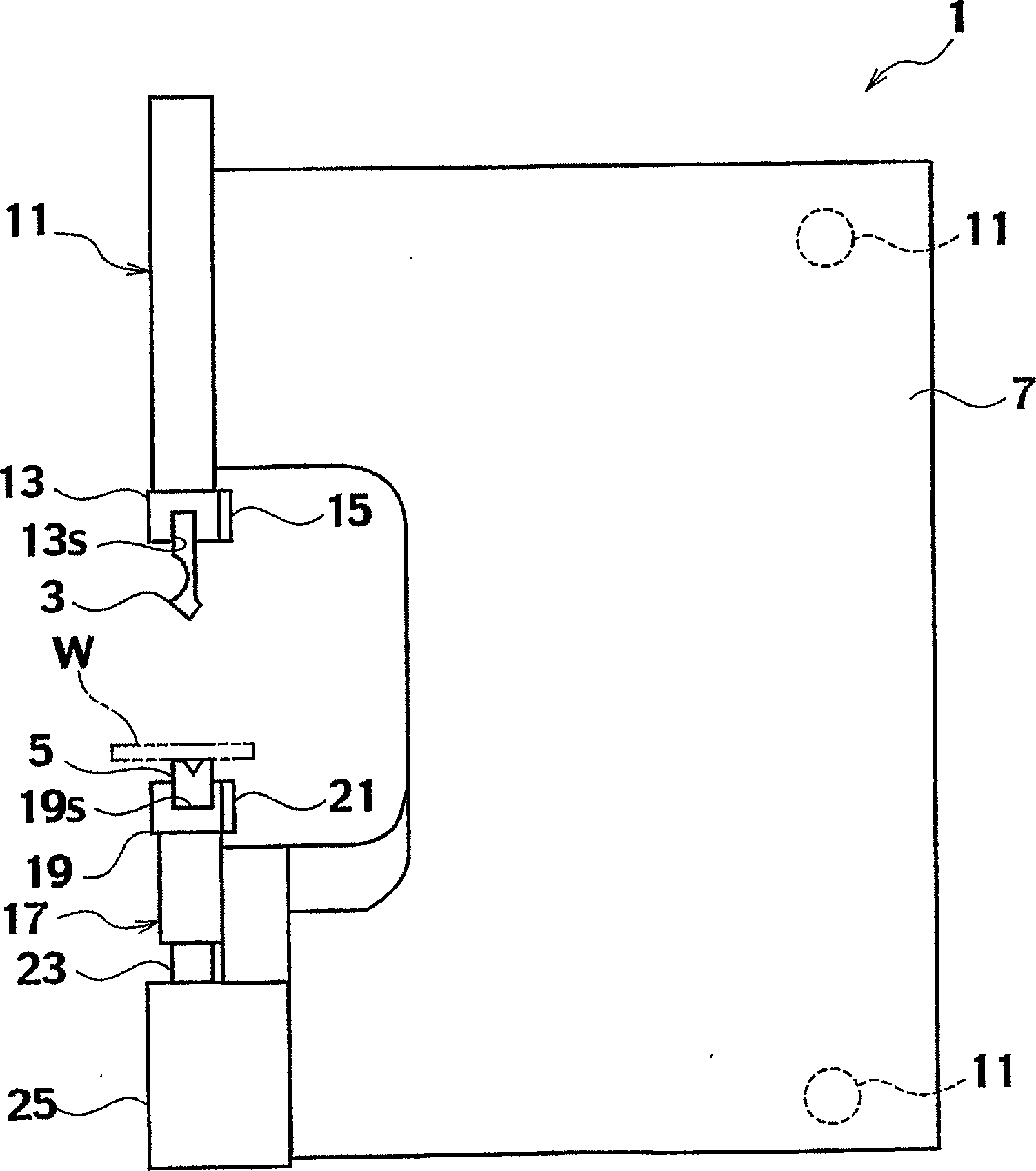
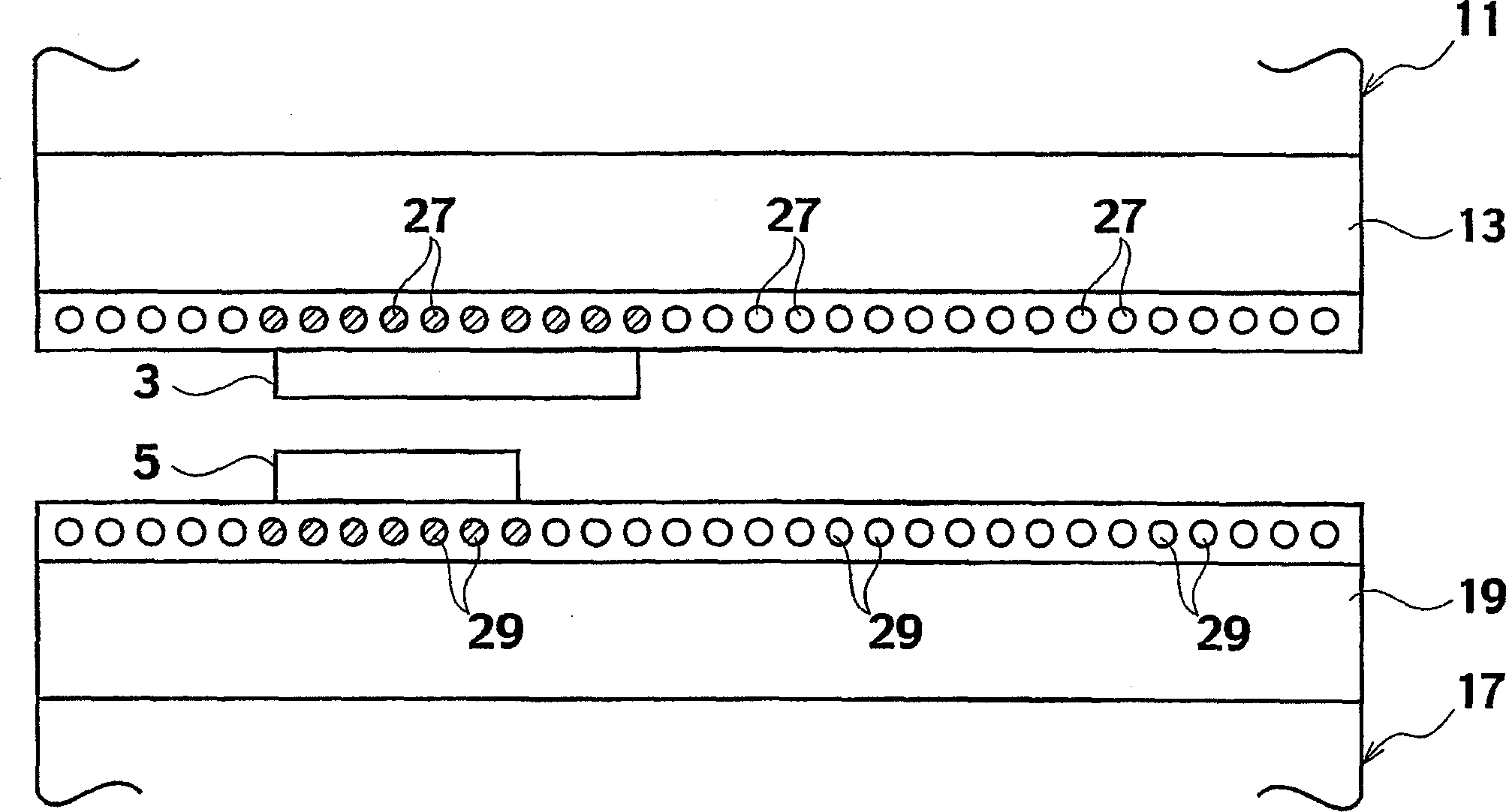
[0087] Refer below Figure 1 to Figure 5 , and the first embodiment of the bending machine according to the present invention will be described.

[0088] first, figure 1 It is a front view explaining the bending machine of 1st Embodiment of this invention, figure 2 It is a side view explaining the bending machine of the first embodiment of the present invention, image 3 It is a schematic diagram illustrating a state in which a plurality of upward index light emitting elements and a plurality of downward index light emitting elements corresponding to mold mounting reference positions in the left and right directions emit light, Figure 4 It is a schematic diagram illustrating a state in which a plurality of downward index light-emitting elements corresponding to workpiece positioning reference positions in the left-right direction emit light, Figure 5 It is a block diagram illustrating the NC apparatus according to Embodiment 1 of the present invention.

[0089] Here, "l...


PUM


Abstract

The present invention relates to a mechanism for positioning a mold and a bending machine equipped with a mechanism for positioning a workpiece. The bending machine (1) has an upper table (11), a lower table (17), an input unit (35) for inputting product information, a bending order determination unit (41) for determining the bending order of workpieces, and a A mold determining unit (39) of the mold required for bending, a layout determining unit (43) determining the layout of the mold, and a position of the workpiece relative to the mold determined by the layout determining unit as the workpiece position The positioning information calculation part (45) calculated by the information, and the guide part (145) for guiding the position of the workpiece to the operator by moving in the left and right direction according to the workpiece position information calculated by the positioning information calculation part .

Description

technical field [0001] The invention relates to a bending machine for bending a workpiece through the cooperation of an upper bending mold and a lower bending mold, in detail, it relates to a mechanism for positioning the mold and a mechanism for positioning the workpiece bending machine. Background technique [0002] Conventionally, as the prior art of the bending machine, there is a device as described in the following Patent Document 1, and this prior art will be briefly described below. [0003] That is, the above-mentioned conventional bending machine bends a plate-shaped workpiece by cooperating with the upper bending die and the lower bending die, and uses a pair of side plates facing left and right and integrally connected as a base plate. The above-mentioned bending machine includes an upper table provided on the upper portion of the pair of side plates, a lower table provided on the lower portion of the certain side plate facing the upper table up and down, and an...

Claims


Application Information

Patent Timeline
IPC IPC(8): B21D5/02
Inventor 丹羽嘉明池田英胜柴田隆浩
Owner AMADA CO LTD
Learn More