Locking device with double spherical hinge bearing structure for pile legs of self-elevating drilling platform

A technology for pile legs and bearing structures of drilling platforms, which is applied to underwater structures, infrastructure engineering, hydraulic engineering, etc., can solve the problems of difficulty in unlocking, inability to effectively utilize the bearing capacity in different ways, and troublesome on-site operations.

Active Publication Date: 2010-10-27
KEEN OFFSHORE ENG CO LTD +1
View PDF0 Cites 21 Cited by
  • Summary
  • Abstract
  • Description
  • Claims
  • Application Information

AI Technical Summary

Problems solved by technology

Moreover, since the platform is equipped with multiple locking devices, the locking operation is completed by platform personnel, which inevitably leads to differences in the carrying capacity of each set of locking devices, and the carrying capacity of each set of devices cannot be effectively utilized.
Moreover, due to the long-term locking of the pile legs, and the changes in the local load of the platform during this process, or the influence of factors such as elastic and plastic deformation of the hull structure, it is generally difficult to unlock in various existing locking devices. phenomenon, which often brings a lot of trouble to on-site operations
Although various types of locking devices have taken some measures to be used in emergency situations, there are many inconveniences in implementation.
For example, the currently widely used sand pad device must be replaced with a new sand pad after the sand pad is used to unlock it before it can continue to be used.

Method used


Image

  • Locking device with double spherical hinge bearing structure for pile legs of self-elevating drilling platform
  • Locking device with double spherical hinge bearing structure for pile legs of self-elevating drilling platform
  • Locking device with double spherical hinge bearing structure for pile legs of self-elevating drilling platform

Examples


Embodiment Construction

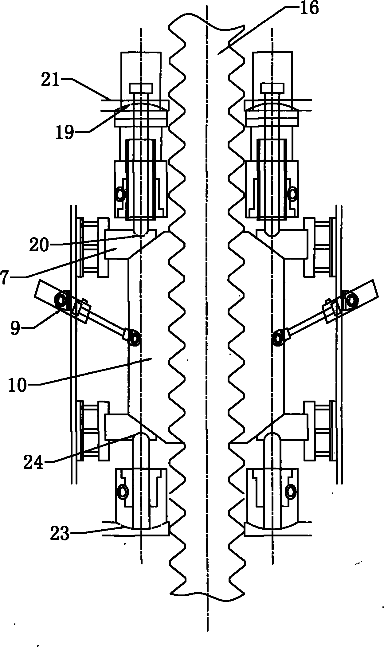
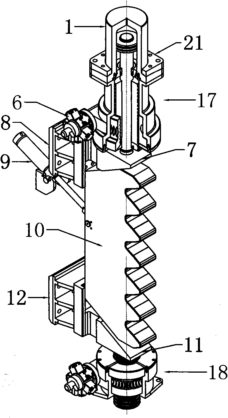
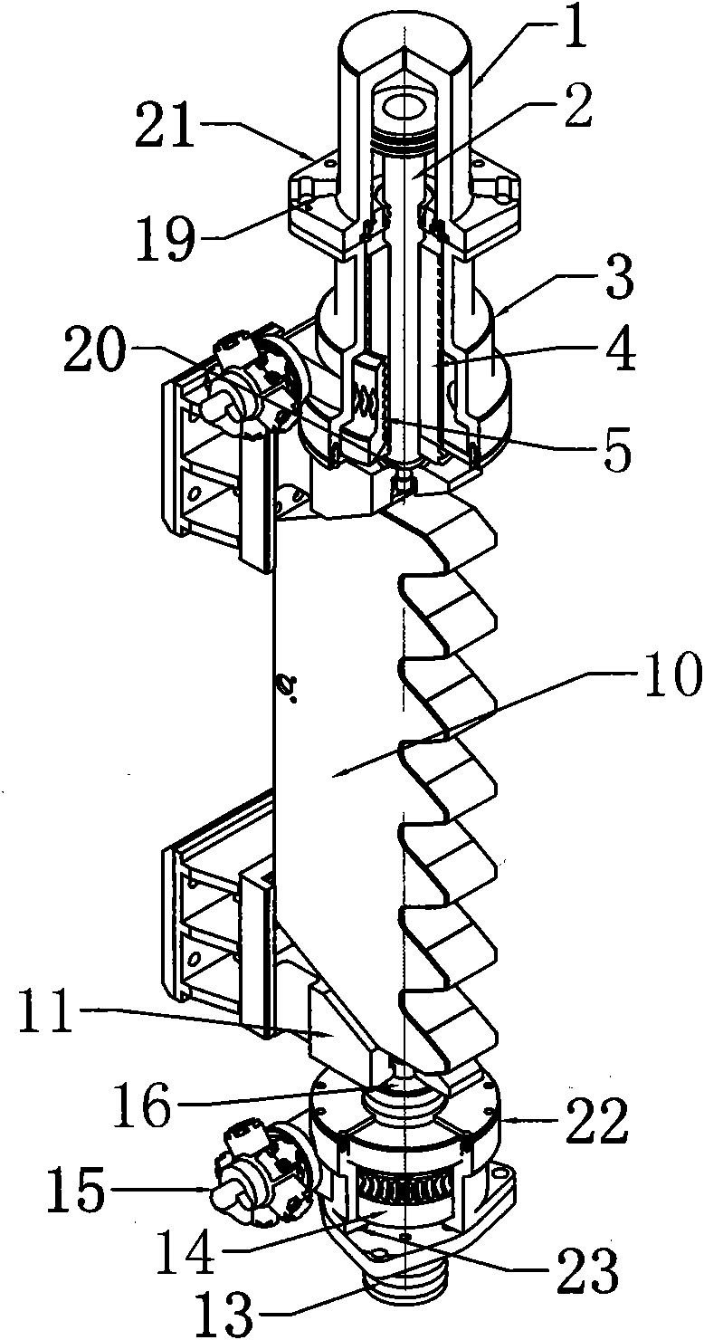
[0015] Attached below figure 1 To attach image 3To further illustrate the present invention, the preferred embodiment of the present invention is: the self-elevating drilling platform leg locking device with double spherical joint bearing structure described in this embodiment, the locking device includes a top locking device Component 17, bottom locking component 18, locking block 10, wherein the locking block 10 is fitted on the leg rack 16 through the teeth, and the carrying platform 21 is provided with a lateral tension cylinder 9, a lateral tension cylinder 9 The cylinder body is installed on the bearing platform 21, and the piston rod of the lateral tension cylinder 9 is hinged with the locking block 10. The top locking assembly 17 and the bottom locking assembly 18 are multiple groups, radially distributed on the outside of the leg rack 16, and assembled on the bearing platform 21 on the upper and lower sides of the locking block 10, and through the top wedge 7. The ...


PUM


Abstract

The invention provides a locking device with hinge with a double spherical hinge bearing structure for pile legs of a self-elevating drilling platform, which comprises a top locking assembly, a bottom locking assembly and a locking block, wherein the locking block is tabled on a pile leg rack through a cog, and the top locking assembly and the bottom locking assembly are respectively assembled on bearing platforms at the upper side and the lower side of the locking block and are respectively contacted with the locking block through a top wedge block and a bottom wedge block; and a top upper spherical hinge, a top lower spherical hinge, a bottom upper spherical hinge and a bottom lower spherical hinge are respectively arranged at the contact places of the top locking assembly and the bottom locking assembly as well as the bearing platform, the top wedge block and the bottom wedge block. With the scheme, the invention not only ensures the effective locking of the platform, but also solves the problem that the locking device is difficult to unlock; and each locking device is uniformly loaded after locking, and the load smoothly transfer between a lifting device and the locking device, thereby greatly saving the operating time of the staff.

Description

Technical field: [0001] The invention relates to the technical field of offshore drilling platforms, in particular to a jack-up drilling platform leg locking device with a double spherical joint bearing structure. Background technique: [0002] The jack-up drilling platform relies on three or four legs to support the weight of the entire platform for offshore operations. Due to the improvement of construction code requirements, most of the jack-up drilling platforms currently built are required to have leg locking devices, so that the platform can reach Storm resistance as required by code. [0003] At present, the existing leg locking devices basically use the self-locking principle of the thread to complete the restraint of the legs from the vertical and horizontal directions, so as to achieve the locking effect. However, there are some functional shortcomings in various forms of existing locking devices. The locking device must be able to independently withstand the load...

Claims


Application Information

Patent Timeline
Patent Type & Authority Applications(China)
IPC IPC(8): E02B17/06
Inventor 崔峰李光远
Owner KEEN OFFSHORE ENG CO LTD
Why Eureka
Try Eureka