Dampness removing structure, steam cooking device and humidity control method

A cooking device and humidity control technology, which is applied to steam cooking utensils, timing control ignition mechanisms, cooking utensils, etc., can solve the problems of difficult humidity control of steam cooking devices, difficulty in steaming food, and low accuracy, and achieves constant temperature and constant temperature. Good humidity effect, avoid inaccurate humidity control, stable internal environment

Active Publication Date: 2020-12-11
VATTI CORP LTD
View PDF8 Cites 4 Cited by
  • Summary
  • Abstract
  • Description
  • Claims
  • Application Information

AI Technical Summary

Problems solved by technology

For example, if the humidity is too high, steamed food with too much water will appear wet; if steam-baked food is too wet, it will not be crispy on the outside and tender on the inside; if the humidity is too low, it will be difficult to steam the food The food will get too dry etc. so the right cooking humidity is needed for the best taste
[0003] The relative humidity inside the steam cooking device is related to the real-time temperature, and the internal temperature is often a dynamic change, which makes it difficult to control the humidity of the steam cooking device, and humidity overshoot occurs during the humidification process, such as real-time humidity If it rises outside the set target relative humidity range, or the real-time temperature suddenly drops, resulting in an increase in relative humidity, etc., the accuracy of humidity control is low, so a method that can quickly remove humidity is designed to ensure the humidity inside the steam cooking device stability is necessary

Method used


Image

  • Dampness removing structure, steam cooking device and humidity control method
  • Dampness removing structure, steam cooking device and humidity control method
  • Dampness removing structure, steam cooking device and humidity control method

Examples


Embodiment 1

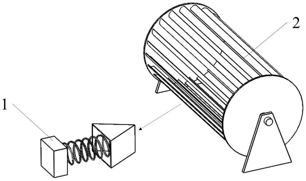
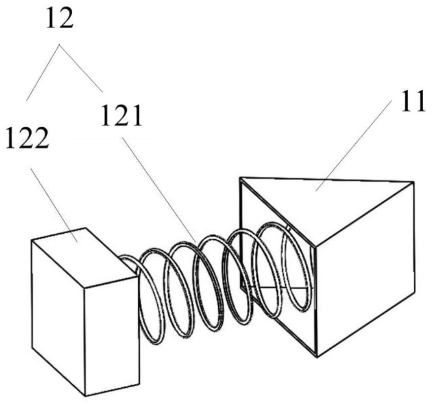
[0056] This embodiment provides a dehumidification structure for steam cooking devices, such as figure 1 with figure 2 As shown, it includes a gas blocking module 1 and a driving module 2; the gas blocking module 1 is arranged above the exhaust port of the steam cooking device, and is used to adjust the opening of the exhaust port, and the driving module 2 is arranged on the on steam cooking appliances;

[0057] The driving module 2 is activated to drive the gas blocking module 1 to move, change the opening of the exhaust port, and adjust the gas discharge volume.

[0058] Specifically, the air blocking module 1 is arranged on the steam cooking device, and is located above the outside of the exhaust port. At this time, the air blocking module 1 does not completely cover the exhaust port, and the driving module 2 is arranged on the steam cooking device; thus, the driving module 2 is started to drive the moving parts in the gas blocking module 1 to move, thereby changing the ...

Embodiment 2

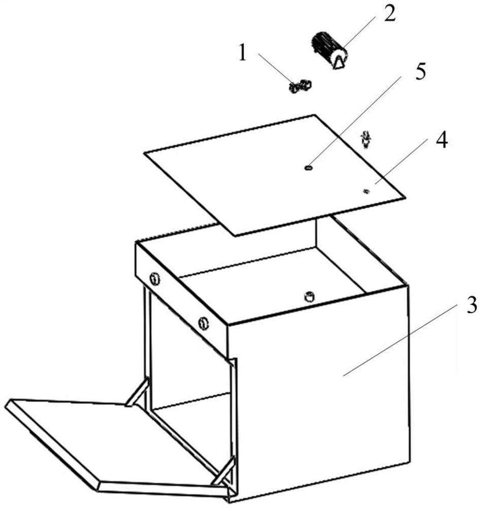
[0075] This embodiment provides a steam cooking device, which includes the dehumidification structure of Embodiment 1, a housing 3, a middle plate 4 and an exhaust port 5, the middle plate 4 is horizontally arranged in the housing 3, and the exhaust The air port 5 is set through the middle plate 4, the gas blocking module 1 is set on the middle plate 4 and is located above the exhaust port 5, and the driving module 2 is set on the middle plate 4 superior.

[0076] In this way, the air-blocking module 1 is driven to move by the driving module 2, and the opening of the exhaust port 5 is changed, so as to realize rapid dehumidification.

[0077] In a specific implementation, the steam cooking device further includes an exhaust hood, an oxygen concentration detection component, and the like.

[0078] In this embodiment, a dehumidification structure is arranged on the middle plate of the steam cooking device. The dehumidification structure includes a gas-blocking module and a driv...

Embodiment 3

[0080] This embodiment provides a humidity control method, which is applied to the steam cooking device in Embodiment 2, and includes the following steps:

[0081] S1, start the steam cooking device, select the cooking mode, and input the preset temperature and preset humidity;

[0082] S2, preheating the inner tank of the cooking device to the preset temperature, when the preset temperature is reached, adjusting the humidity of the inner tank to the preset humidity, that is, adjusting the oxygen concentration of the inner tank is the oxygen concentration corresponding to the preset humidity;

[0083] S3, collecting the real-time temperature of the inner container, and obtaining a real-time oxygen concentration controllable range according to the real-time temperature, preset humidity, and controllable humidity corresponding to the cooking mode;

[0084] Wherein, the controllable humidity corresponding to the cooking mode is obtained according to the cooking mode;

[0085] S...


PUM


Abstract

The invention discloses a dampness removing structure, a steam cooking device and a humidity control method. The dampness removing structure is used for the steam cooking device and comprises an air blocking module and a driving module; the air blocking module is arranged above the exterior of an exhaust port of the steam cooking device and used for adjusting the opening degree of the exhaust port, and the driving module is arranged on the steam cooking device; and the driving module is started to drive the air blocking module to move, the opening degree of the exhaust port is changed, and thegas discharge amount is adjusted. Accordingly, by arranging the dampness removing structure, the driving module is started to drive the air blocking module to change the opening degree of the exhaustport, then the gas discharge amount is adjusted, and the rapid dampness removing effect is achieved; and meanwhile, by obtaining the real-time oxygen concentration controllable range according to thereal-time temperature of an inner container, the preset humidity and the controllable humidity corresponding to the cooking mode, finally, whether humidification and/or dampness removing is conductedor not is determined according to the comparison relation between the real-time oxygen concentration and the real-time oxygen concentration controllable range, and the problem that humidity control is not precise due to real-time temperature change of the inner container is effectively avoided.

Description

technical field [0001] The invention belongs to the technical field of steam cooking devices, and in particular relates to a dehumidification structure, a steam cooking device and a humidity control method. Background technique [0002] The taste of food cooking is related to the ingredients and the cooking environment, and the cooking environment mainly includes temperature and humidity. When the temperature is kept appropriate, the environmental humidity has a great influence on the quality of the cooking taste. For example, if the humidity is too high, steamed food with too much water will appear wet; if steam-baked food is too wet, it will not be crispy on the outside and tender on the inside; if the humidity is too low, it will be difficult to steam the food The food will get too dry etc. so the right cooking humidity is needed for the best taste. [0003] The relative humidity inside the steam cooking device is related to the real-time temperature, and the internal te...

Claims


Application Information

Patent Timeline
Patent Type & Authority Applications(China)
IPC IPC(8): A47J27/04A47J36/38A47J36/32
CPCA47J27/04A47J36/38A47J36/32A47J2027/043
Inventor 许胜涛麦伟添陈权明潘叶江
Owner VATTI CORP LTD
Why Eureka
Try Eureka