
A kind of cross-flow ceramic membrane filter in petrochemical field

A petrochemical and ceramic membrane technology, applied in the fields of filtration and separation, purification by filtration, chemical instruments and methods, etc., can solve problems such as unfavorable petrochemical production, accumulation of impurities in ceramic membranes, trouble, etc., and achieve the effect of improving chemical production efficiency.

Active Publication Date: 2021-04-02
大庆惠博普石油机械设备制造有限公司
View PDF9 Cites 0 Cited by
  • Summary
  • Abstract
  • Description
  • Claims
  • Application Information

AI Technical Summary

Problems solved by technology

[0002] The ceramic membrane has excellent thermal stability and chemical stability, and the impurity removal efficiency is high. However, when the ceramic membrane removes impurities, the surface of the ceramic membrane is prone to produce filter cakes, and the accumulation of filter cakes is likely to cause low impurity removal efficiency of the ceramic membrane.
It is not conducive to petrochemical production. Petroleum production and filtration generally adopts dead-end filtration of ceramic membranes. Although dead-end filtration has high filtration efficiency, dead-end filtration can easily cause impurities to accumulate on ceramic membranes. It is troublesome to clean or replace ceramic membranes regularly. , for this reason, need a kind of petrochemical field cross-flow ceramic membrane filter

Method used


Image

  • A kind of cross-flow ceramic membrane filter in petrochemical field
  • A kind of cross-flow ceramic membrane filter in petrochemical field
  • A kind of cross-flow ceramic membrane filter in petrochemical field

Examples


Embodiment Construction

[0030]The technical solutions of the present invention will be further described below with reference to the accompanying drawings.

[0031]The drawings are for exemplary description, which is merely a schematic diagram, rather than the experiment, and is not to be understood to be in this patent; in order to better illustrate the embodiments of the invention, there will be omitted, Enlarge or shrink does not represent the size of the actual product; some well-known structures and descriptions thereof may be understood in the drawings in the drawings.

[0032]The same or similar reference numerals in the drawings of the present invention correspond to the same or similar components; in the description of the present invention, it is to be understood that if the term "on", "", "," left "," right " The orientation or position of the instructions such as "inside", "outside" is based on the orientation or positional relationship shown in the drawings, is merely description of the present inve...


PUM


Abstract

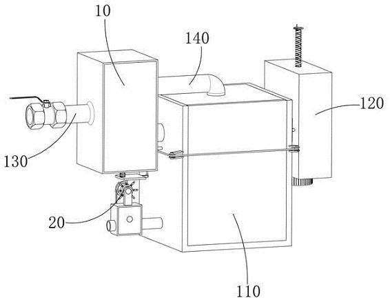
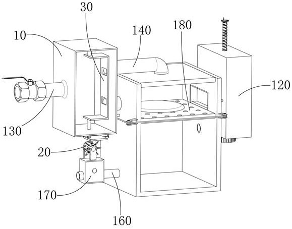
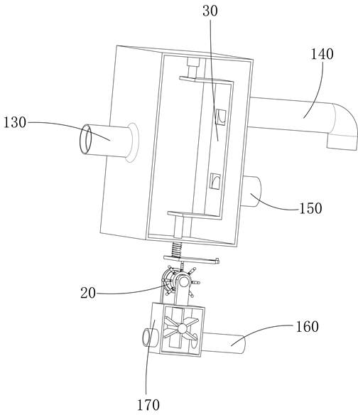
The invention discloses a cross-flow type ceramic membrane filter in the field of petrochemical engineering, which comprises a feeding box body, a filtering box body and an impurity removal box body;the feeding box body, the filtering box body and the impurity removal box body are all of cuboid structures, the filtering box body is positioned between the feeding box body and the impurity removalbox body, and a communicating pipe I and a communicating pipe II are communicated between the feeding box body and the filtering box body; one end of the first communicating pipe is communicated withthe side wall of the feeding box body, the other end of the first communicating pipe is communicated with the top of the filtering box body, petroleum flows into the feeding box body through the liquid inlet pipe and then is discharged into the filtering box body through the first communicating pipe and the second communicating pipe, and the petroleum flowing into the feeding box body through thefirst communicating pipe makes contact with the ceramic membrane to be filtered at the dead end. Petroleum flowing into the feeding box body through the second communicating pipe makes contact with the ceramic membrane for cross-flow filtration; when filter cakes are accumulated on the surface of the ceramic membrane, the flowing speed of the petroleum flowing into the mounting shell through the third communicating pipe is low, the amount of the petroleum flowing into the filtering box body through the second communicating pipe is increased, and dead end filtration is converted into cross-flowfiltration.

Description

Technical field[0001]The present invention relates to the field of petrochemical technology, and more particularly to a variable flow ceramic membrane filter in petrochemical field.Background technique[0002]The ceramic membrane has excellent thermal stability and chemical stability, with high hetero efficiency, but after the ceramic film is incurden, the surface of the ceramic film is easily produced, and the deposit of the filter cake is easily low. It is not conducive to petrochemical production, and oil production filtration is generally filtered through the dead end of the ceramic membrane. Although the dead end filtration is high, the dead end filter is easily accumulated, and the impurity stack of the ceramic membrane is required. It is necessary to clean up or replace the ceramic membrane. For this reason, there is a need for a variable flow ceramic membrane filter for petrochemical field.Inventive content[0003]In order to solve the deficiencies of the prior art, the object o...

Claims


Application Information

Patent Timeline
Patent Type & Authority Patents(China)
IPC IPC(8): B01D35/12B01D35/16C10G31/09
CPCB01D35/12B01D35/16C10G31/09
Inventor 林明青
Owner 大庆惠博普石油机械设备制造有限公司
Learn More