Cutter grinding device

A tool and sliding installation technology, applied in grinding drive devices, manufacturing tools, grinding workpiece supports, etc., can solve problems such as inability to use different grinding methods, inability to adjust the height of the tool, and the inability of the blade to face grinding, etc., to achieve a stable fixation effect. Effect

Inactive Publication Date: 2020-12-11
哈尔滨市阿城区胜达建筑材料厂
View PDF1 Cites 1 Cited by
  • Summary
  • Abstract
  • Description
  • Claims
  • Application Information

AI Technical Summary

Problems solved by technology

[0004] 1. The way of grinding the tool is too simple, it is impossible to control the grinding angle and direction of the tool, that is, it is impossible to use different grinding methods for different types of tools
[0005] 2. Unable to adjust the distance of a single grinding, unable to adapt to the length of different knives
[0006] 3. The height of the device where the tool is located cannot be adjusted, and the blades of different widths of the tool cannot face the grinding position, and the re-grinding effect is poor

Method used


Image

  • Cutter grinding device
  • Cutter grinding device
  • Cutter grinding device

Examples


specific Embodiment approach 1

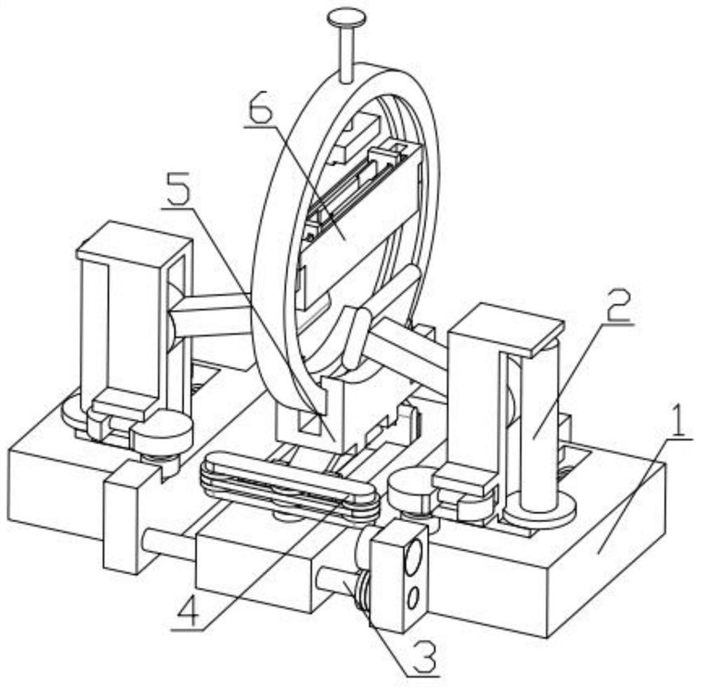
[0036] Combine below Figure 1-11Describe this embodiment, a tool grinding device, including a toggle and base 1, a grinding adjustment mechanism 2, a position adjustment mechanism 3, a one-way power mechanism 4, an angle adjustment mechanism 5 and a tool fixing mechanism 6, the grinding adjustment mechanism 2 Slidingly installed in the groove provided on the toggle and base 1, the two sides of the position adjustment mechanism 3 are respectively fixedly installed with the toggle and base 1, the one-way power mechanism 4 is fixedly installed on the position adjustment mechanism 3, and the angle adjustment mechanism 5 is fixedly installed on the position adjustment mechanism 3, and the tool fixing mechanism 6 is fixedly installed on the angle adjustment mechanism 5.

specific Embodiment approach 2

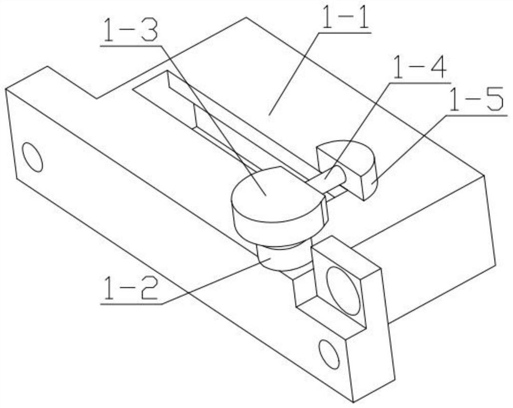
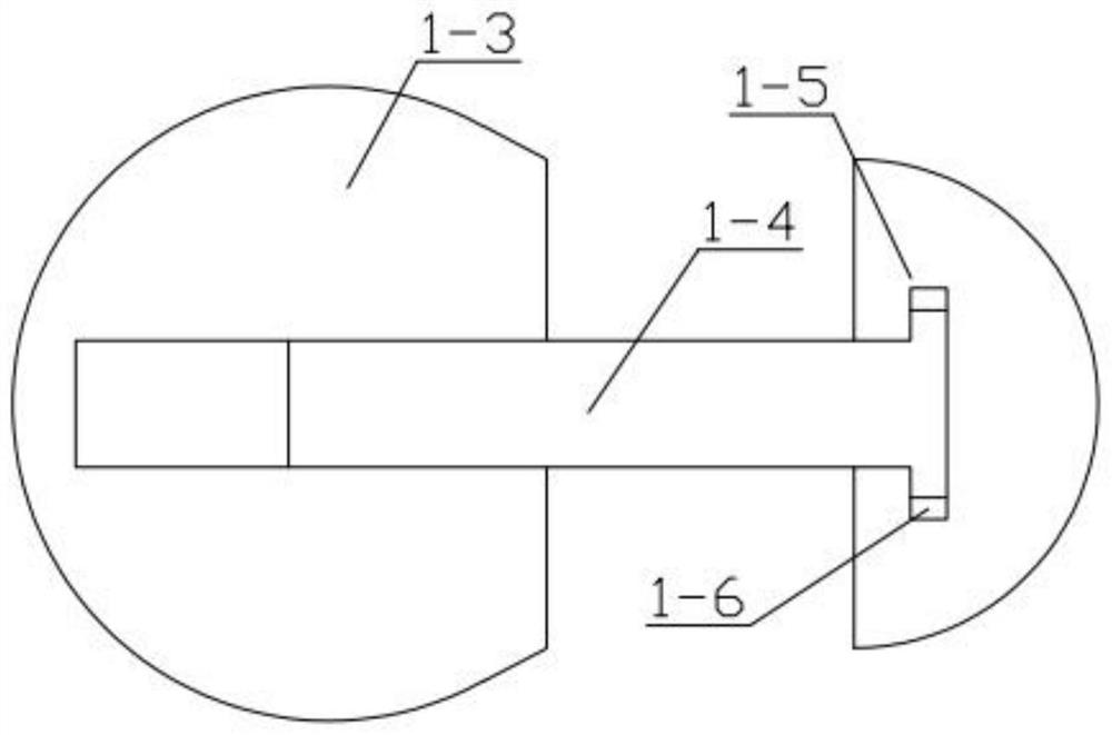
[0038] Combine below Figure 1-11 Describe this embodiment, this embodiment will further explain the first embodiment, the toggle and base 1 includes a base 1-1, a bottom gear 1-2, a cam connector 1-3, an adjustment threaded rod 1-4, a semicircle Pieces 1-5, rubber ring 1-6, the bottom gear 1-2 is rotatably installed in the groove provided on the base 1-1, the cam connector 1-3 is fixedly installed on the bottom gear 1-2, adjust the threaded rod 1 -4 is threadedly connected with the cam connector 1-3, the other end of the adjusting threaded rod 1-4 is rotatably mounted on the adjusting threaded rod 1-4, and the rubber ring 1-6 is fixedly mounted on the adjusting threaded rod 1-4.

specific Embodiment approach 3

[0040] Combine below Figure 1-11 Describe this embodiment, this embodiment will further explain the second embodiment, the grinding adjustment mechanism 2 includes a support spring 2-1, a stand 2-2, a manual turntable 2-3, a worm 2-4, a worm wheel 2- 5. The connecting rod 2-6, the grinding stone 2-7, the stand 2-2 is slidably installed in the groove provided on the base 1-1, and one end of the support spring 2-1 is fixedly installed on the stand 2-2, The other end of the support spring 2-1 is fixedly installed on the base 1-1, the manual turntable 2-3 is rotatably installed in the groove provided on the stand 2-2, the manual turntable 2-3 is fixedly connected with the worm screw 2-4, The other end of the worm 2-4 is rotatably installed in the groove provided on the stand 2-2, the worm 2-4 is meshed with the worm wheel 2-5, and the worm wheel 2-5 is rotatably installed in the recess provided on the stand 2-2. In the groove, the worm gear 2-5 is fixedly connected with the conn...


PUM


Abstract

The invention relates to the field of machining and manufacturing, in particular to a cutter grinding device. The cutter grinding device comprises shifting gears and bases, grinding adjusting mechanisms, a position adjusting mechanism, a one-way power mechanism, an angle adjusting mechanism and a cutter fixing mechanism. The grinding adjusting mechanisms are mounted in grooves in the shifting gears and bases in a sliding manner. The shifting gears and bases are fixedly mounted on the two sides of the position adjusting mechanism correspondingly, the one-way power mechanism is fixedly mounted on the position adjusting mechanism, the angle adjusting mechanism is fixedly mounted on the position adjusting mechanism, and the cutter fixing mechanism is fixedly mounted on the angle adjusting mechanism. The device has the function of adjusting the grinding angle and the grinding direction, different grinding manners are adopted for different kinds of cutters, the functions that the grinding effect is optimal and the cutter height is specifically adjusted are achieved, the device adapts to cutters with different widths, the function of adjusting the single-time grinding distance is achieved, and the device adapts to cutters with different lengths.

Description

technical field [0001] The invention relates to the field of machining and manufacturing, in particular to a tool grinding device. Background technique [0002] Knives are an indispensable tool in people's daily life. Knives will become blunt after a period of use. Generally, users will use a grinding stone to polish the edge of the knife. However, the technique and strength of the grinding will often damage the edge and shorten the The service life of knives, the inventors found that a patent has been authorized in the prior art, and the patent number is CN201610837194.X. A rapid knife sharpening device has the function of sharpening knives, but there are some disadvantages. [0003] The disadvantages of this invention are: [0004] 1. The tool grinding method is too simple to control the grinding angle and direction of the tool, that is, it is impossible to use different grinding methods for different types of tools. [0005] 2. It is impossible to adjust the distance of...

Claims


Application Information

Patent Timeline
IPC IPC(8): B24B3/36B24B3/00B24B41/06B24B47/22
CPCB24B3/00B24B3/36B24B41/06B24B47/22
Inventor 高会明
Owner 哈尔滨市阿城区胜达建筑材料厂
Why Eureka
Try Eureka