Supercharge Your Innovation With Domain-Expert AI Agents!

Quick locking mechanism, mounting device and automobile

A locking mechanism, fast technology, applied in the direction of electric vehicles, power devices, electric power devices, etc., can solve the problems of easy deformation, stress concentration, etc., and achieve the effect of fast limit installation

Pending Publication Date: 2020-12-11
ZHEJIANG JIZHI NEW ENERGY AUTOMOBILE TECH CO LTD +1
View PDF0 Cites 0 Cited by
  • Summary
  • Abstract
  • Description
  • Claims
  • Application Information

AI Technical Summary

Problems solved by technology

[0007] In order to solve the above technical problems, the present invention provides a fast locking mechanism, which uses the hinged part hinged to the locking housing as the locking mechanism to replace the traditional way of locking with a small ball on top of a large ball, and solves the current problem. There are technical problems such as technical stress concentration and easy deformation

Method used


Image

  • Quick locking mechanism, mounting device and automobile
  • Quick locking mechanism, mounting device and automobile
  • Quick locking mechanism, mounting device and automobile

Examples


Embodiment 1

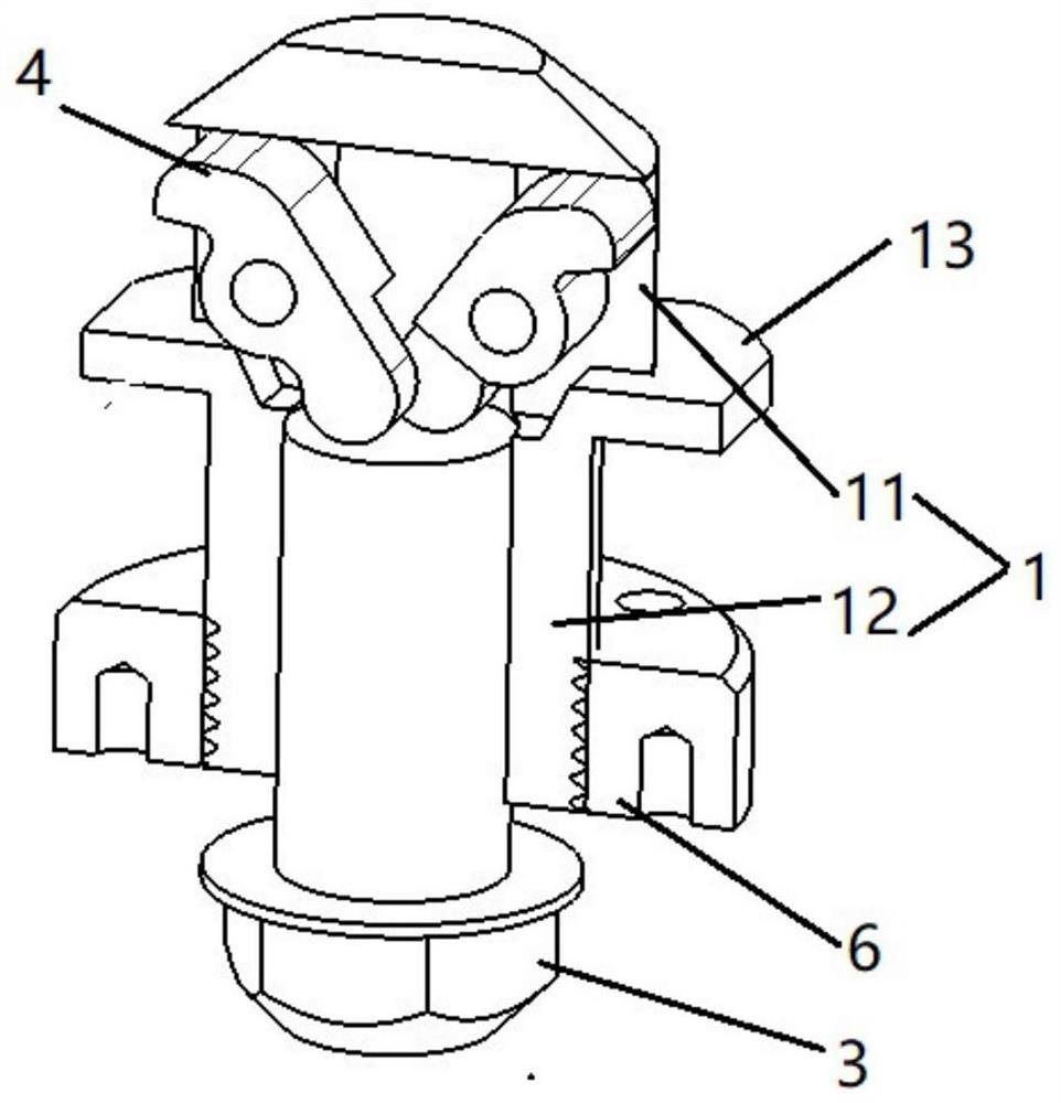
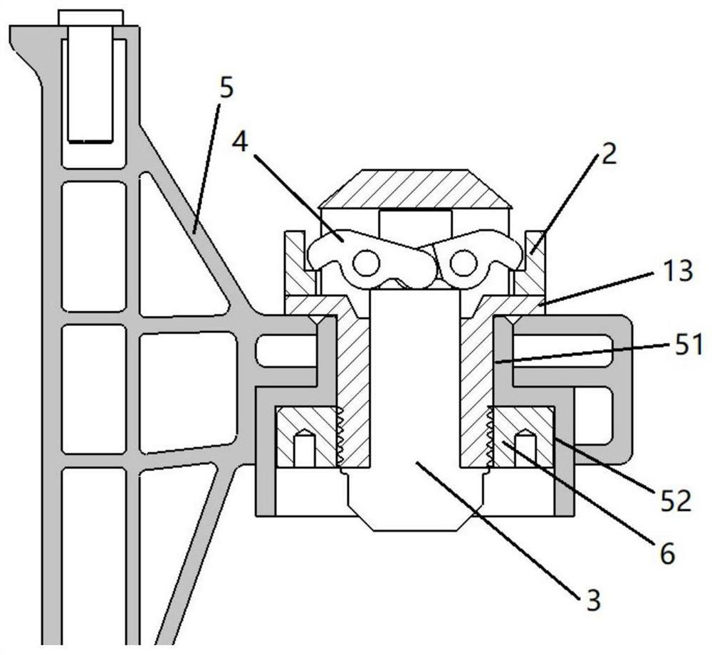
[0031] like Figure 1-4 As shown, it is a quick locking mechanism, including a locking housing 1 , a locking connector 2 , a jacking device 3 and a locking member 4 ; wherein the locking housing 1 is installed on a mounting beam 5 .

[0032] The locking piece 4 and the locking housing 1 are hinged through the hinge shaft 4, wherein a return spring, such as a coil spring, etc. is provided on the hinge shaft. Reset is also possible. The locking part 4 is provided with a locking end 41 and a driving end 42 on both sides of the hinge point. The locking housing 1 is a hollow structure jacking device 3, which is specifically a locking bolt and is at least partly arranged in the locking housing. The locking housing 1 It has a locking part 11 and a connecting part 12. The locking part 4 is hinged to the locking part 11. The jacking device 3 is connected to the connecting part 12. The jacking device 3 is a locking bolt. The inner cavity of the connecting part 12 has a The thread matc...

Embodiment 2

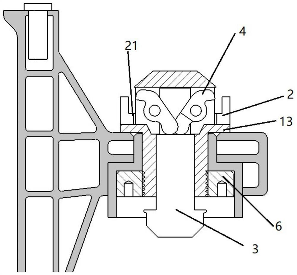
[0037] The difference from Embodiment 1 is that the jacking device is a piston rod, which is driven by a pneumatic device and can move axially relative to the locking housing 1. Compared with Embodiment 1, this embodiment uses a piston rod as a reciprocating The locking and releasing driving mechanism makes the driving method more rapid and direct.

[0038] Through the above specific embodiments, the following technical effects are achieved:

[0039] (1) The locking piece is hinged to the locking shell, and the rotation of the locking piece relative to the locking shell is controlled through the cooperation of the jacking device to realize locking and disengagement. The cooperation of the jacking device and the locking piece replaces the original locking method of the small ball on the top of the big ball, and there will be no technical problems in the original technology that cause deformation due to excessive concentration of stress due to the contact and cooperation between...


PUM


Abstract

The invention relates to a quick locking mechanism which comprises a locking shell, a locking connecting piece, a jacking device and a locking piece. The locking piece is hinged to the locking shell,the locking piece is provided with a driving end and a locking end on the two sides of a hinge point, the locking shell is of a hollow structure, at least part of the jacking device is arranged in thelocking shell and can move in the axial direction relative to the locking shell, and the driving end is driven by the jacking device to move. The locking piece rotates relative to the locking shell,when the jacking device moves to a first position, the locking piece and the locking connecting piece are mutually locked through the locking end, and when the jacking device moves to a second position, the locking end of the locking piece and the locking connecting piece are separated from each other. According to the mechanism, an articulation piece articulated with the locking shell is used asa locking mechanism to replace the traditional mode of locking by using a small ball with a large ball top, so that the technical problems of stress concentration and easiness in deformation in the prior art are solved.

Description

technical field [0001] The invention relates to the field of electric vehicles, in particular to a quick locking mechanism on the electric vehicle, a battery fixing and installing device using the locking mechanism, and a car with the battery fixing and installing device. Background technique [0002] The power supply methods of the former electric vehicle power battery are generally divided into two methods: plug-in charging with the car and battery replacement, among which there are two modes of plug-in charging: slow charging and fast charging. The plug-in charging method has the following defects: 1. The initial investment cost of the battery is relatively large, which hinders the popularization of electric vehicles to a certain extent; 2. The charging time is too long, at least 2 to 4 hours, which is comparable to the refueling of ordinary cars Compared with electric vehicles, it takes too long to recharge energy, which is very inconvenient and far from meeting people's...

Claims


Application Information

Patent Timeline
Patent Type & Authority Applications(China)
IPC IPC(8): B60K1/04B60L53/80H01M2/10
CPCB60K1/04B60K2001/0455B60L53/80Y02T10/70Y02T10/7072
Inventor 张志强韩磊王志海
Owner ZHEJIANG JIZHI NEW ENERGY AUTOMOBILE TECH CO LTD
Features
  • R&D
  • Intellectual Property
  • Life Sciences
  • Materials
  • Tech Scout
  • Unparalleled Data Quality
  • Higher Quality Content
  • 60% Fewer Hallucinations
Learn More