Clutch pedal device of electronic clutch system

A clutch pedal, electronic clutch technology, applied in clutches, mechanical drive clutches, control devices, etc., can solve the problem of not setting a clutch master cylinder, avoid leg injuries, avoid inconsistent feeling, and improve marketability.

Pending Publication Date: 2020-12-11
HYUNDAI MOTOR CO LTD +1
View PDF0 Cites 0 Cited by
  • Summary
  • Abstract
  • Description
  • Claims
  • Application Information

AI Technical Summary

Problems solved by technology

[0008] In addition, the electronic clutch system does not provide a clutch master cylinder, so that a separate mechanical configuration for adjusting the initial position (return position) of the clutch pedal is also required

Method used


Image

  • Clutch pedal device of electronic clutch system
  • Clutch pedal device of electronic clutch system
  • Clutch pedal device of electronic clutch system

Examples


Embodiment Construction

[0042] Hereinafter, a clutch pedal device of an electronic clutch system according to an exemplary embodiment of the present invention will be described in detail with reference to the accompanying drawings.

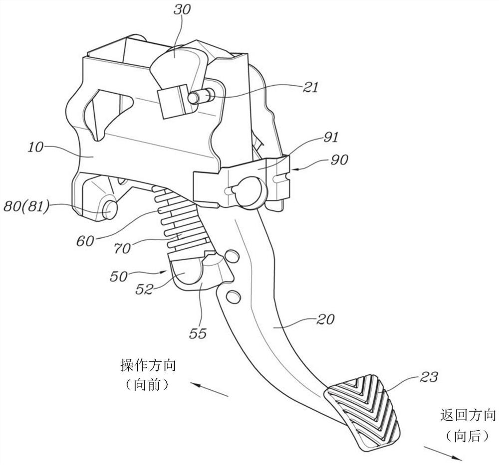
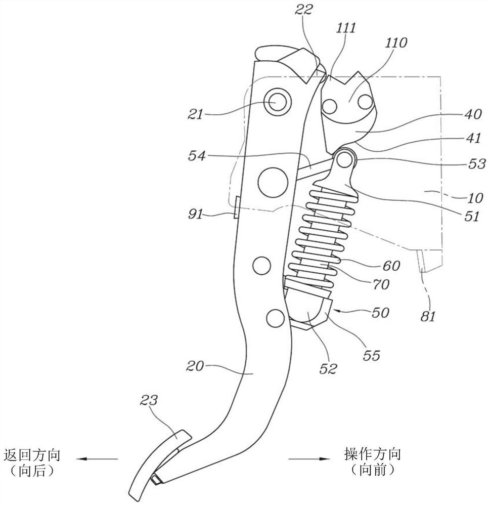
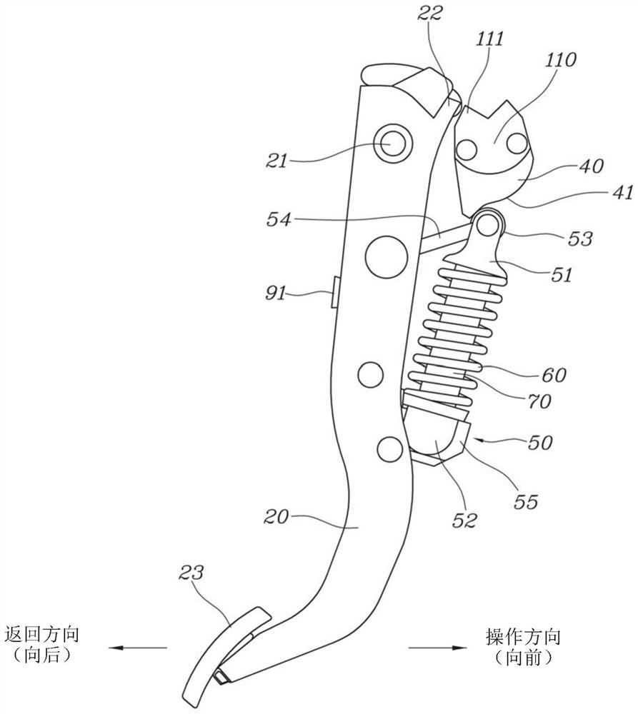
[0043] Such as Figures 1 to 12 Shown, according to the present invention, the clutch pedal device of described electronic clutch system comprises: pedal member 10 and clutch pedal 20; It is rotatably coupled to the pedal member 10 about a pedal shaft 21 .

[0044] A pedal sensor 30 connected to the clutch pedal 20 is fixed to one side of the pedal member 10 such that a rotation angle is measured during operation of the clutch pedal 20 and the rotation angle of the clutch pedal 20 measured by the pedal sensor 30 is sent to the control unit. The control unit receives various signals such as the signal of the pedal sensor 30 and the engine RPM, and automatically calculates an optimum clutch operation time most suitable for the state of the vehicle to control the operation...


PUM


Abstract

The invention relates to a clutch pedal device of an electronic clutch system, in which the full stroke position and the initial position (return position) of a clutch pedal (20) are adjusted by meansof a front stop device (80) and a rear stop device (90) on a pedal member (10) and the clutch pedal (20), respectively.

Description

technical field [0001] The present invention generally relates to a clutch pedal device for an electronic clutch system, and more particularly, to a clutch pedal device for an electronic clutch system in which a pedal member and a clutch pedal are provided with controls for controlling the clutch pedal's initial position, return position and Stops at full travel position. Background technique [0002] Typically, a manual transmission vehicle includes a clutch arrangement. The clutch device is disposed between the flywheel and the input shaft of the transmission, and functions to control the power of the engine transmitted to the transmission as required. [0003] When performing a gear shift, a driver first depresses a clutch pedal for operation to release connection of a clutch device provided in a vehicle. The driver then manipulates the shift lever to perform a shift toward a desired shift level and takes his / her foot off the clutch pedal to reconnect the clutch device ...

Claims


Application Information

Patent Timeline
Patent Type & Authority Applications(China)
IPC IPC(8): B60K23/02
CPCB60K23/02B60K2023/025G05G1/44G05G5/03F16D23/12G05G1/30
Inventor 金容喜闵顶宣
Owner HYUNDAI MOTOR CO LTD
Why Eureka
Try Eureka