
Breaker non-full-phase function testing device

A function test and circuit breaker technology, which is applied in the direction of circuit breaker test, measuring device, instrument, etc., can solve the problems of high number of actions, short circuit of control circuit, difficult cooperation, etc., and achieve improved safety performance, improved work efficiency, inspection work intuitively

Pending Publication Date: 2020-12-11
STATE GRID CORP OF CHINA +1
View PDF8 Cites 0 Cited by
  • Summary
  • Abstract
  • Description
  • Claims
  • Application Information

AI Technical Summary

Problems solved by technology

The non-full-phase function needs to test a total of twelve circuit breaker auxiliary nodes, the number of actions is large, and it is easy to miss
[0004] In the traditional method, three people are required to cooperate to complete the work, which requires a large number of people, is difficult to cooperate, and takes a long time. Multiple tests will cause damage to the circuit breaker
Once the short circuit jumps and the closing circuit is the outlet, it is impossible to check the correctness of the wiring, which will easily cause the two sets of control circuits to short-circuit each other and DC grounding. At the same time, this method requires multiple manual closings, which greatly increases the number of circuit breaker operations. Affect the life of the circuit breaker
Mistakes in the non-full-phase function test of the circuit breaker will cause accidents: when the non-full-phase function pressure plate is put into use, the circuit breaker will trip directly, causing the line to trip by mistake; Short circuit, resulting in the situation that the two sets of control circuits are both grounded, which eventually leads to misoperation of the busbar protection and tripping of the busbar by mistake

Method used


Image

  • Breaker non-full-phase function testing device
  • Breaker non-full-phase function testing device

Examples


Embodiment 1

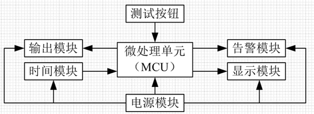
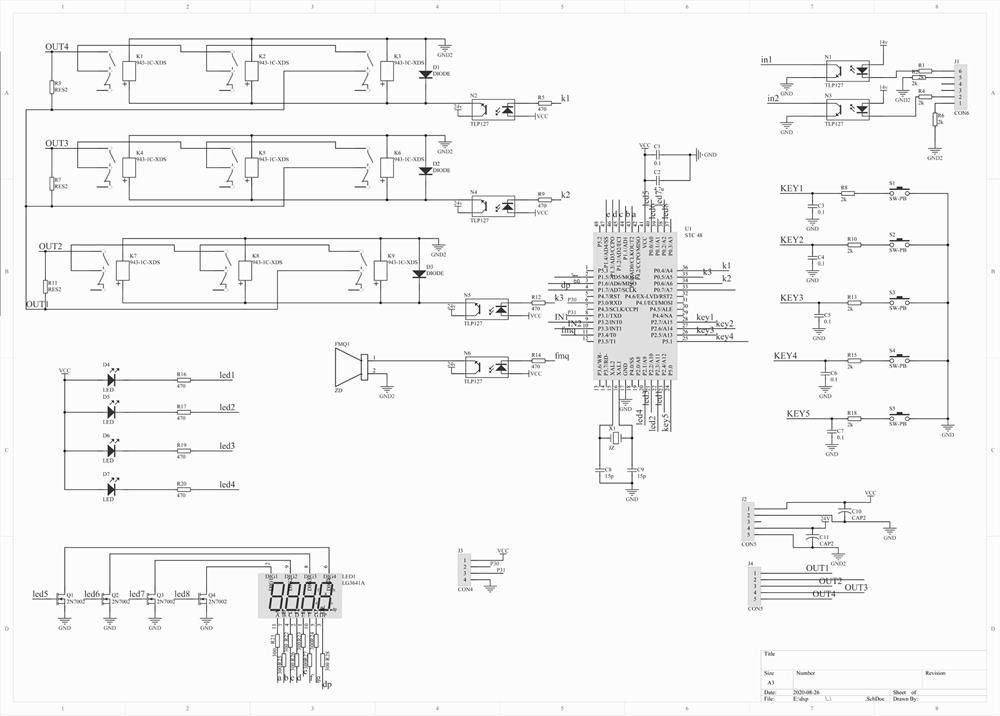
[0036] This embodiment provides a non-full-phase functional testing device for a circuit breaker, which includes a power supply module, an alarm module, an output module, a micro-processing unit MCU, a display module, a test button and a time module.

[0037] Further, the power supply module is electrically connected to the alarm module, output module, MCU, display module, test button and time module respectively.

[0038] The power supply module provides electric energy for the alarm module, the output module, the micro-processing unit MCU, the display module, the test button and the time module respectively.

[0039] Further, the power supply module converts the AC 220V into two power supply isolation outputs, one of which is rectified and filtered by BG400, and then converted into a 5V regulated output VCC1 by DC-DC, which is respectively supplied to the micro-processing unit MCU, display module, test button, The time module and the alarm module are powered; the other one i...

Embodiment 2

[0043] This embodiment provides a non-full-phase functional testing device for a circuit breaker, which includes a power supply module, an alarm module, an output module, a micro-processing unit MCU, a display module, a test button and a time module.

[0044] Further, the power supply module is electrically connected to the alarm module, output module, MCU, display module, test button and time module respectively.

[0045] The power supply module provides electric energy for the alarm module, the output module, the micro-processing unit MCU, the display module, the test button and the time module respectively.

[0046] Further, the power supply module converts the AC 220V into two power supply isolation outputs, one of which is rectified and filtered by BG400, and then converted into a 5V regulated output VCC1 by DC-DC, which is respectively supplied to the micro-processing unit MCU, display module, test button, The time module and the alarm module are powered; the other one i...

Embodiment 3

[0052] This embodiment provides a non-full-phase functional testing device for a circuit breaker, which includes a power supply module, an alarm module, an output module, a micro-processing unit MCU, a display module, a test button and a time module.

[0053] Further, the power supply module is electrically connected to the alarm module, output module, MCU, display module, test button and time module respectively.

[0054] The power supply module provides electric energy for the alarm module, the output module, the micro-processing unit MCU, the display module, the test button and the time module respectively.

[0055] Further, the power supply module converts the AC 220V into two power supply isolation outputs, one of which is rectified and filtered by BG400, and then converted into a 5V regulated output VCC1 by DC-DC, which is respectively supplied to the micro-processing unit MCU, display module, test button, The time module and the alarm module are powered; the other one i...


PUM


Abstract

The invention discloses a breaker non-full-phase function testing device which comprises a power supply module, an alarm module, an output module, a micro-processing unit (MCU), a display module, a test button and a time module. The power supply module, the alarm module, the output module, the display module, the test button and the time module are connected with the micro-processing unit (MCU), and the test button is used for driving the micro-processing unit (MCU) to start a task. The device is used for driving the micro-processing unit (MCU) to start a task. By using the device, the problemthat the inspection work is completed by three persons in cooperation in the past is solved, one person can independently complete the inspection work, and the working efficiency is greatly improved.

Description

technical field [0001] The invention belongs to the technical field of relay protection, and in particular relates to a non-full-phase functional testing device for a circuit breaker. Background technique [0002] At present, the non-full-phase function test of the circuit breaker is an indispensable inspection content in the infrastructure acceptance and maintenance pre-test of the circuit breaker in the relay protection profession. [0003] The staff continues to use the traditional method for inspection, and at least three people are required to cooperate to complete the work. One person performs non-full-phase pressure plate switching and switch opening and closing at the HSBC cabinet or terminal box, and one person monitors it. At the same time, another person needs to check the indication position of the operation box and the recording signal in front of the protective screen. The traditional non-full-phase test requires a large number of people, which is dangerous, a...

Claims


Application Information

Patent Timeline
Patent Type & Authority Applications(China)
IPC IPC(8): G01R31/327
CPCG01R31/3277
Inventor 尚柳王乐张坤张岩坡张韶光渠红涛王亚强刘海锋王昭雷马宜军
Owner STATE GRID CORP OF CHINA
Learn More