
Fixing device for linear laser output

A fixed device, line laser technology, applied in the field of laser beam expansion, can solve the problems of deviation, complex alignment, difficult to achieve alignment, etc., to avoid deviation, simplify the alignment process, and improve the efficiency of use

Active Publication Date: 2020-12-11
MECH MIND ROBOTICS TECH LTD
View PDF1 Cites 1 Cited by
  • Summary
  • Abstract
  • Description
  • Claims
  • Application Information

AI Technical Summary

Problems solved by technology

From the point of view of the adjustment process of the device, its alignment method is complicated and it is difficult to achieve alignment. In addition, if the top wire falls off during subsequent use, there will be a large deviation in the relative position between the laser beam and the prism

Method used


Image

  • Fixing device for linear laser output
  • Fixing device for linear laser output
  • Fixing device for linear laser output

Examples


Embodiment Construction

[0046] Embodiments of the present application are described in detail below, and examples of the embodiments are shown in the drawings, wherein the same or similar reference numerals denote the same or similar elements or elements having the same or similar functions throughout. The embodiments described below by referring to the figures are exemplary, and are intended to explain the present application, and should not be construed as limiting the present application.

[0047] A fixing device for line laser output provided by an embodiment of the present application is described below with reference to the accompanying drawings.

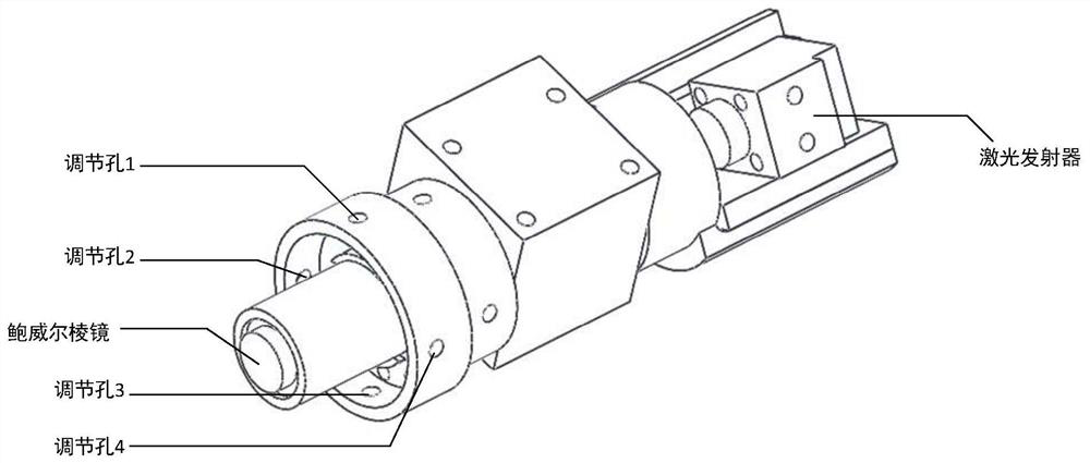
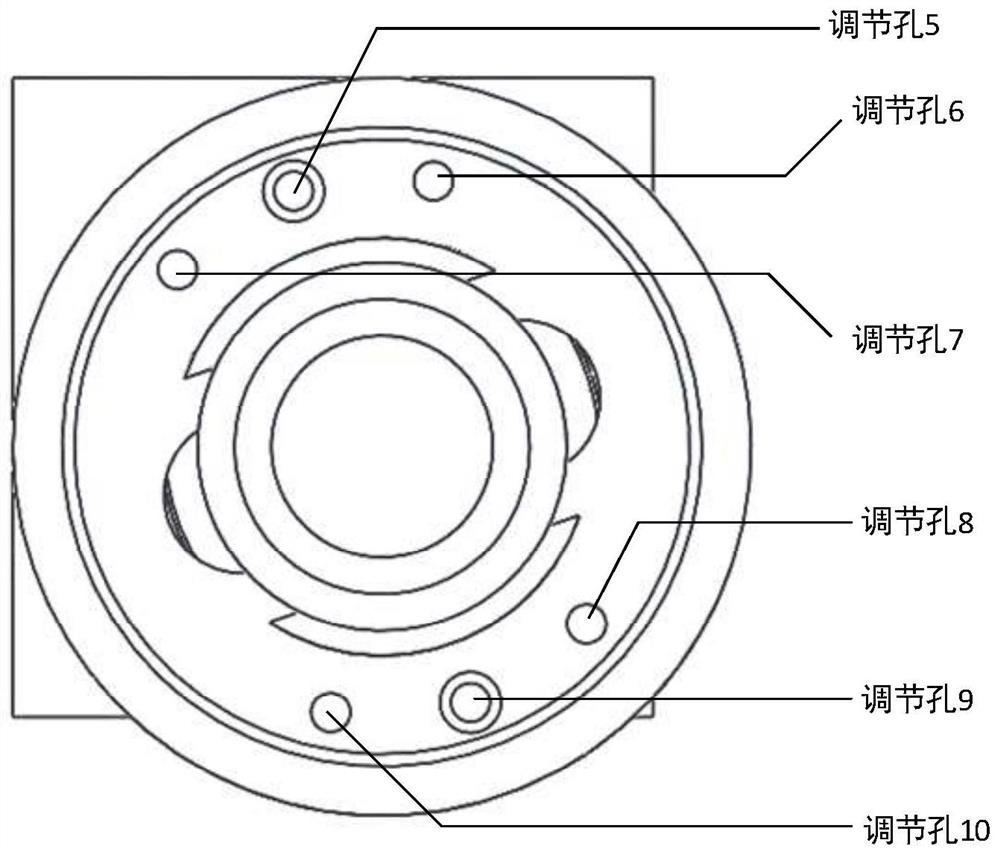
[0048] like figure 2- As shown in FIG. 3 , the fixing device provided by the present application in some embodiments includes: laser beam expander 100: the laser beam expander 100 is axially provided with a laser through hole 101 for passing through the laser beam; The emitter embedding groove 102 of the laser injection end, the peripheral wall of ...


PUM


Abstract

The invention provides a fixing device used for linear laser output. The fixing device comprises a laser beam expanding cylinder, wherein a laser through hole for allowing laser beams to pass throughis arranged in the axial direction of the laser beam expanding cylinder; an emitter embedding groove which is formed in the laser incident end of the laser through hole, wherein the peripheral wall ofthe emitter embedding groove is coaxial with the peripheral wall of the laser through hole, and the bottom wall of the emitter embedding groove is perpendicular to the peripheral wall of the laser through hole, so that the output port of the laser emitter is aligned with the laser through hole, and then the laser beams are incident along the axis of the laser through hole; and a Powell prism embedding groove which is formed in the laser emitting end of the laser through hole, wherein the peripheral wall of the Powell prism embedding groove is coaxial with the peripheral wall of the laser through hole, and the bottom wall of the Powell prism embedding groove is perpendicular to the peripheral wall of the laser through hole; therefore, the non-cylindrical part of the Powell prism is embedded into the Powell prism embedding groove, and the axis of the Powell prism coincides with the axis of the laser through hole. Compared with the prior art, the axial alignment process of the laser beamand the Powell prism is simplified, and the use efficiency is improved.

Description

technical field [0001] The present application relates to the technical field of laser beam expansion, in particular to a fixing device for line laser output. Background technique [0002] With the popularization of laser applications, the requirements for lasers in various fields are gradually increasing from the application point of view, such as the need to output the laser in a fixed shape, or require the laser to carry no less than a certain value of energy when projected onto a certain plane. In the field of laser scanning imaging, the laser needs to be output in the form of a "one" straight line. Normally, the laser beam is input into the Powell prism for shaping to output a "one"-shaped laser, but it is difficult to align the laser beam with the center of the Powell prism, that is, it is difficult for the laser beam to enter along the axis of the Powell prism. In the prior art, there is a fixing device as shown in FIG. 1 , which can realize the aforementioned alignm...

Claims


Application Information

Patent Timeline
IPC IPC(8): G02B7/18F16M7/00F16M11/04
CPCG02B7/1805F16M11/04F16M7/00G02B7/022G02B27/0972G02B19/0014Y02P10/25H01S5/02253H01S5/02326
Inventor 王艳超吴筱丁有爽邵天兰
Owner MECH MIND ROBOTICS TECH LTD
Learn More