Storage link monitoring system and method

A monitoring system and link technology, applied in hardware monitoring, instrumentation, electrical and digital data processing, etc., can solve the problems of low storage subsystem troubleshooting efficiency and low storage subsystem operating efficiency, so as to improve the troubleshooting efficiency and improve the Signal quality, the effect of real-time detection

Active Publication Date: 2020-12-11
SUZHOU LANGCHAO INTELLIGENT TECH CO LTD
View PDF3 Cites 2 Cited by
  • Summary
  • Abstract
  • Description
  • Claims
  • Application Information

AI Technical Summary

Problems solved by technology

[0005] This application provides a storage link monitoring system and method to solve the problem of low efficiency in

Method used


Image

  • Storage link monitoring system and method
  • Storage link monitoring system and method
  • Storage link monitoring system and method

Examples


Embodiment 1

[0056] The storage link in this embodiment includes: a RAID card connected in sequence, multiple cables, a backplane and a hard disk, multiple cables connected in series, and multiple cables from the signal input end to the signal output end according to the signal transmission direction It is defined in turn as: the first cable, the second cable...the Nth cable, and the Nth cable is the last cable. The number of cables in the storage link depends on the actual application scenario, and multiple cables are of equal length.

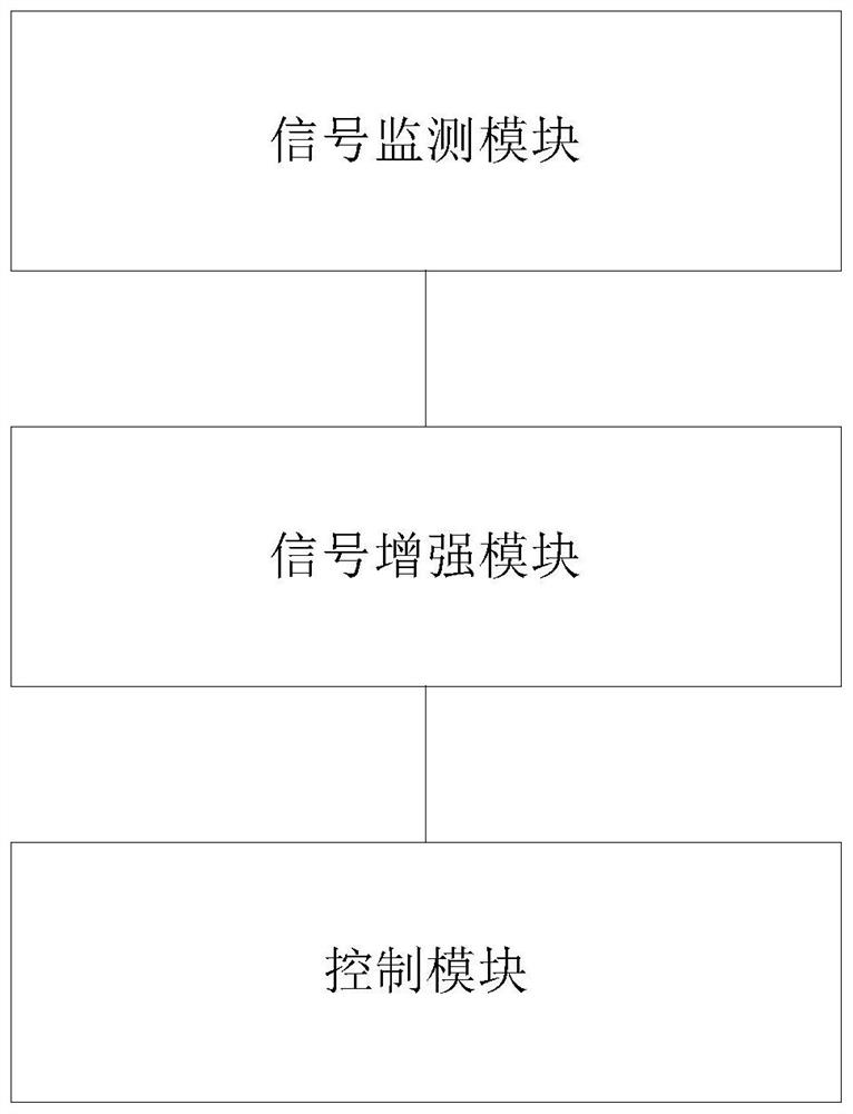
[0057] see figure 1 , figure 1 It is a schematic flowchart of a storage link monitoring system provided in the embodiment of the present application. Depend on figure 1 It can be seen that the storage link monitoring system in this embodiment mainly includes three parts: a signal monitoring module, a signal enhancement module and a control module.

[0058] Among them, the signal monitoring module is used to collect the voltage signal of the collection ...

Embodiment 2

[0090] exist Figure 1-Figure 7 On the basis of the illustrated embodiment see Figure 8 , Figure 8 It is a schematic structural diagram of a storage link monitoring method provided in the embodiment of the present application. Depend on Figure 8 It can be seen that the storage link monitoring method in this embodiment mainly includes:

[0091] S1: Collect the voltage signal of the collection points of the storage link. The collection points include: the signal output end of the RAID card, the signal transmitting end of each cable, the signal receiving end of the backplane, and the signal transmitting end of the backplane.

[0092] Specifically, step S1 includes:

[0093] S11: For any collection point, collect the voltage signal of any collection point in the storage link multiple times to obtain multiple voltage values.

[0094] S12: Take the median of multiple voltage values.

[0095] S13: Use the median result as the voltage value of any collection point.

[0096] ...


PUM


Abstract

The invention discloses a storage link monitoring system and method. The system comprises a signal monitoring module, a signal enhancement module and a control module. The method comprises the steps of collecting a voltage signal of a storage link collection point, judging whether a voltage value of an Nth cable is smaller than a set voltage threshold value or not according to the voltage signal,and when the voltage value of the Nth cable is smaller than the set voltage threshold value, performing signal enhancement on the corresponding cable to enable the voltage value of the Nth cable to reach the set voltage threshold value; and when the signal is enhanced and the voltage value of the Nth cable is smaller than a set voltage threshold, analyzing the voltage signal of the acquisition point, and determining a faulty link according to the voltage signal of the acquisition point. According to the method and the device, the troubleshooting efficiency of the storage link can be effectively improved, the monitoring accuracy of the storage link is improved, and the running stability of the storage link is improved.

Description

technical field [0001] The present application relates to the technical field of server storage monitoring, in particular to a storage link monitoring system and method. Background technique [0002] The storage subsystem is an important part used for data storage in the server, and generally the storage subsystem includes: RAID (Redundant Array of Independent Disks, Redundant Array of Independent Disks, Redundant Array of Independent Disks) cards, cables, backplanes, hard disks and other devices. It is an important technical issue to monitor the entire storage subsystem to ensure the stability of the entire storage subsystem, thereby avoiding data loss. [0003] The current method for monitoring the storage subsystem usually uses flag bits to detect the signal quality of PCIE (peripheral component interconnect express, a high-speed serial computer expansion bus standard). Specifically, the RAID controller is used to assign different flag bits, and when a data storage error...

Claims


Application Information

Patent Timeline
IPC IPC(8): G06F11/30
CPCG06F11/3034
Inventor 毛心宇
Owner SUZHOU LANGCHAO INTELLIGENT TECH CO LTD
Why Eureka
Try Eureka