
Zero-sequence current mutual inductance device

A mutual induction device and zero-sequence current technology, which is applied to inductors, transformer/inductor cores, circuits, etc., can solve the problems of zero-sequence current mutual induction devices such as temperature rise, core loss, and power waste, so as to save manpower , the effect of improving efficiency

Pending Publication Date: 2020-12-11
QINGYUAN POWER SUPPLY BUREAU OF GUANGDONG POWER GRID CO LTD
View PDF3 Cites 0 Cited by
  • Summary
  • Abstract
  • Description
  • Claims
  • Application Information

AI Technical Summary

Problems solved by technology

The existence of eddy current not only leads to the waste of electric energy, but also increases the temperature of the zero-sequence current mutual induction device, causing serious accidents
[0005] In view of the above problems, it is necessary to develop a zero-sequence current mutual induction device to solve the problems of eddy currents generated by the iron core due to electromagnetic induction, which cause losses and the inconvenient disassembly and assembly of the closed zero-sequence current mutual induction device.

Method used


Image

  • Zero-sequence current mutual inductance device
  • Zero-sequence current mutual inductance device
  • Zero-sequence current mutual inductance device

Examples


no. 1 example

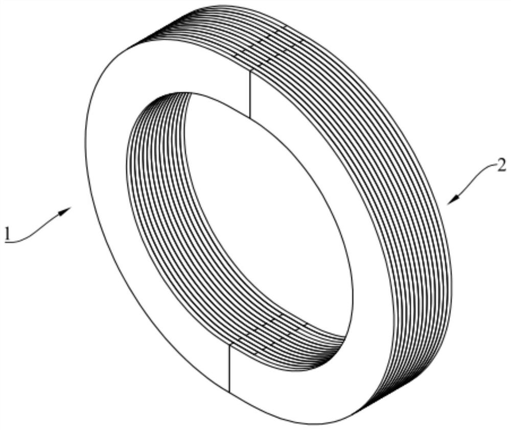
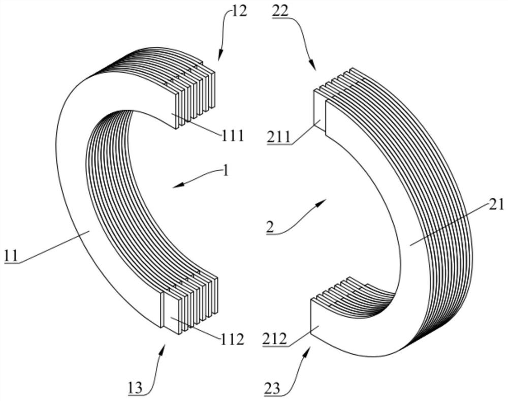
[0038] This embodiment provides a zero-sequence current mutual induction device. Such as Figure 1-Figure 3 As shown, the zero-sequence current mutual induction device includes a first iron core 1 and a second iron core 2, the first iron core 1 is formed by stacking a plurality of first steel sheets 11 insulated from each other, and the second iron core 2 is formed by stacking mutually insulated A plurality of second steel sheets 21 are stacked, and the number of first steel sheets 11 is equal to the number of second steel sheets 21 . The first iron core 1 and the second iron core 2 are detachably connected end to end in order to form a ring structure, and in the ring structure, the first steel sheet 11 and the second steel sheet 21 are in contact one by one, and the size of the ring structure should be It can ensure that three phase wires can pass through at the same time.

[0039] The iron core in the traditional zero-sequence current mutual induction device is a closed ring...

no. 2 example

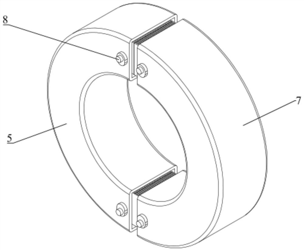
[0060] This embodiment provides a zero-sequence current mutual induction device, which adds locking mechanisms for the first iron core 1 and the second iron core 2 on the basis of the first embodiment.

[0061] Such as Figure 4-Figure 6 As shown, in order to ensure the stability of the entire device after the first iron core 1 and the second iron core 2 are closed to form a ring structure, the zero-sequence current mutual induction device also includes an insulated first bolt 3, a first nut 31, a second bolt 4 and The second nut 41, the first end 111 and the third end 211 are all provided with a concentric first through hole 5, the first bolt 3 passes through the first through hole 5 of the first end 111 and the third end 211 and connects with the first The nut 31 is threaded; the second end 112 and the fourth end 212 are all provided with a concentric second through hole 9, and the second bolt 4 passes through the second through hole 9 of the second end 112 and the fourth en...


PUM


Abstract

The invention discloses a zero-sequence current mutual inductance device, and relates to the field of power fault detection. The zero-sequence current mutual inductance device comprises first iron cores and second iron cores, and each first iron core is formed by stacking a plurality of first steel sheets which are insulated from one another; and each second iron core is formed by stacking a plurality of second steel sheets which are insulated from one another, the number of the second steel sheets is equal to that of the first iron cores, the first iron cores and the second iron cores are detachably connected end to end in sequence to form an annular structure, and in the annular structure, the first steel sheets and the second steel sheets abut against each other in a one-to-one correspondence mode. The zero-sequence current mutual inductance device is convenient to assemble and disassemble, live-line operation is carried out in use, and the eddy current loss of the whole device canbe reduced.

Description

technical field [0001] The invention relates to the field of electric fault detection, in particular to a zero-sequence current mutual induction device. Background technique [0002] With the wide application of various power systems in industrial production and daily life, devices that can accurately and conveniently measure current are needed to monitor the safe and effective operation of the power system. The zero-sequence current mutual inductance device mainly has two purposes, one is to be placed in the circuit for a long time as a circuit protection device; the other is to be placed in the circuit for a short time as a detection device for the normal operation of the circuit. In the actual three-phase four-wire circuit system, the vector sum of the currents flowing in the three phase wires should be zero. In order to monitor in real time or manually detect whether the circuit system is operating normally, it is necessary to pass the three phase wires through the zero...

Claims


Application Information

Patent Timeline
Patent Type & Authority Applications(China)
IPC IPC(8): H01F27/245H01F27/26H01F27/34H01F38/30
CPCH01F27/245H01F27/34H01F27/263H01F38/30H01F2027/348H01F2038/305
Inventor 王伟黄石华吴昆泰李宗元赖家文
Owner QINGYUAN POWER SUPPLY BUREAU OF GUANGDONG POWER GRID CO LTD
Learn More