Supercharge Your Innovation With Domain-Expert AI Agents!

Magnetic element

A technology of magnetic components and magnetic cores, applied in the direction of electrical components, transformer/inductor cores, transformer/inductor components, etc., can solve problems such as increasing cost and increasing area, and achieve the effect of reducing quantity and cost

Pending Publication Date: 2020-12-11
HEFEI SILERGY SEMICON TECH CO LTD
View PDF0 Cites 1 Cited by
  • Summary
  • Abstract
  • Description
  • Claims
  • Application Information

AI Technical Summary

Problems solved by technology

However, the SMD skeleton will increase the area occupied by the magnetic components and increase the cost

Method used


Image

  • Magnetic element
  • Magnetic element
  • Magnetic element

Examples


Embodiment Construction

[0038] Hereinafter, the present invention will be described in more detail with reference to the accompanying drawings. In the various drawings, the same components are denoted by similar reference numerals. For the sake of clarity, various parts in the drawings have not been drawn to scale. Also, some well-known parts may not be shown. For simplicity, the structure obtained after several steps can be described in one figure. In the following, many specific details of the present invention are described, such as the structure, material, size, process and technique of each constituent part, for a clearer understanding of the present invention. However, the invention may be practiced without these specific details, as will be understood by those skilled in the art.

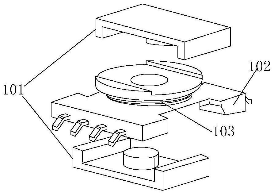
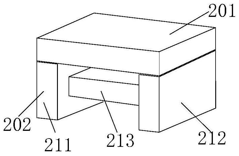
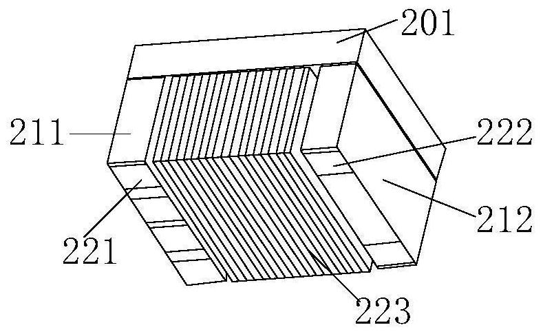
[0039] The present invention provides a magnetic element, which includes a cover plate and a magnetic core body, the magnetic core body includes a first side column and a second side column, and a center connecti...


PUM


Abstract

The invention discloses a magnetic element, which comprises a cover plate and a magnetic core body, and is characterized in that the magnetic core body comprises a first side column, a second side column and a middle column connected between the first side column and the second side column, and a winding is wound on the middle column; and the cover plate is fixed on the upper surfaces of the firstside column and the second side column. According to the invention, the small size of the magnetic element is realized, and the cost is reduced.

Description

technical field [0001] The invention relates to the field of magnetic components, in particular to a magnetic element. Background technique [0002] With the increase of switching frequency, the miniaturization of magnetic components has become a trend in the industry. figure 1 According to the existing multi-output transformer structure, the magnetic element consists of three parts: a magnetic core 101 , an SMD skeleton 102 and a wire package 103 . However, the SMD skeleton will increase the area occupied by the magnetic components and increase the cost. Contents of the invention [0003] In view of this, the present invention proposes a small-sized transformer to reduce its production cost. [0004] According to the first aspect of the present invention, a magnetic element is proposed, including a cover plate and a magnetic core body, the magnetic core body includes a first side column and a second side column, and a magnetic element connected to the first side column ...

Claims


Application Information

Patent Timeline
IPC IPC(8): H01F27/26H01F27/30
CPCH01F27/266H01F27/306
Inventor 代克危建颜佳佳
Owner HEFEI SILERGY SEMICON TECH CO LTD
Features
  • R&D
  • Intellectual Property
  • Life Sciences
  • Materials
  • Tech Scout
  • Unparalleled Data Quality
  • Higher Quality Content
  • 60% Fewer Hallucinations
Learn More