Hidden fire hydrant

A fire hydrant and concealed technology, which is applied in the field of concealed fire hydrants, can solve the problems of safety risks, pedestrian obstruction, and easy collision, etc., and achieve the effect of simple and convenient operation and improved safety

Inactive Publication Date: 2020-12-15
俞先祥
View PDF6 Cites 0 Cited by
  • Summary
  • Abstract
  • Description
  • Claims
  • Application Information

AI Technical Summary

Problems solved by technology

[0003] Fire hydrants are generally installed on both sides of the road and protrude from the ground, which hinders pedestrians. During walking, they are prone to collisions and pose a safety risk

Method used


Image

  • Hidden fire hydrant
  • Hidden fire hydrant
  • Hidden fire hydrant

Examples


Embodiment 1

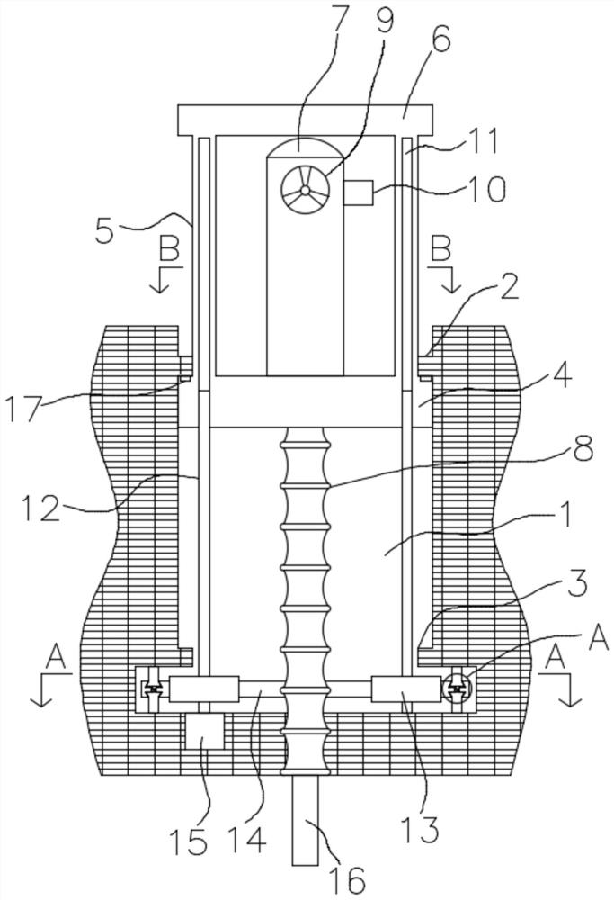
[0027] refer to Figure 1-5 , a concealed fire hydrant, comprising a cylindrical groove 1 on the ground, an annular groove is formed at the inner bottom of the groove 1, and a first The annular protrusion 2 and the second annular protrusion 3 are slidingly connected with a bottom plate 4 in the groove 1 and between the first annular protrusion 2 and the second annular protrusion 3. The upper end of the bottom plate 4 is uniformly integrated with its own axis as the center of the circle. A plurality of connecting columns 5 are formed, the upper ends of the plurality of connecting columns 5 are integrally formed with a top plate 6, and the middle part of the upper end of the bottom plate 4 is fixedly equipped with a fire hydrant body 7, which is the prior art, and the water inlet end of the fire hydrant body 7 is connected with a telescopic The pipe 8 and the upper end of the telescopic pipe 8 are set through the bottom plate 4, the lower end of the telescopic pipe 8 passes thro...

Embodiment 2

[0038]refer to Figure 6-7 The difference between this embodiment and Embodiment 1 is that the lifting device includes a limiting groove 23 jointly opened in the connecting column 5 and the bottom plate 4, the limiting groove 23 is slidingly connected to the limiting rod 24, and the inner top of the annular groove The wall is evenly provided with a plurality of side grooves 26, and an interlayer is formed between the side grooves 26 and the groove 1. The upper end of the interlayer is provided with an installation groove connected with the side grooves 26 and the groove 1, and two inner walls on both sides of the installation groove are rotated and installed. Guide wheel 25, and two guide wheels 25 are arranged corresponding to groove 1, side groove 26, and traction rope 27 is guided, and the inner bottom wall of annular groove is fixedly installed with small hoist 28, and the driving equipment of small hoist 28 adopts worm gear to reduce speed Machine, low speed and self-lock...


PUM


Abstract

The invention discloses a hidden fire hydrant. The hidden fire hydrant comprises a cylindrical groove formed in the ground, wherein an annular groove is formed in the inner bottom of the groove; a first annular protrusion and a second annular protrusion are sequentially arranged on the inner circumferential wall of the groove from top to bottom; a bottom plate is slidably connected in the groove and between the first annular protrusion and the second annular protrusion; a plurality of connecting columns are uniformly and integrally formed at the upper end of the bottom plate with the axis of the bottom plate as the circle center; a top plate is integrally formed at the upper ends of the connecting columns; a fire hydrant body is fixedly installed in the middle of the upper end of the bottom plate; a telescopic pipe is connected to the water inlet end of the fire hydrant body; the upper end of the telescopic pipe penetrates through the bottom plate; and the lower end of the telescopic pipe penetrates through the inner bottom surface of the groove and is connected with a water inlet pipe. The hidden fire hydrant has the advantages that the fire hydrant body is stored in the groove when not in use, the top plate is flush with the ground and does not protrude out of the ground, pedestrians are not affected, and the safety is improved.

Description

technical field [0001] The invention relates to the technical field of fire hydrants, in particular to a hidden fire hydrant. Background technique [0002] A fire hydrant is an outdoor ground fire water supply facility. It is used to supply water to fire trucks or directly connect with hoses and water guns for fire extinguishing. It is a special facility for outdoor necessary fire water supply. The upper part of the utility model is exposed to the ground, the mark is obvious, and the utility model is convenient to use. It consists of parts such as valve body, elbow, valve seat, valve disc, drain valve, valve stem and interface. Above-ground fire hydrants are necessary fire-fighting equipment in cities, especially in urban areas and areas with fewer rivers, to ensure fire-fighting water supply needs. [0003] Fire hydrants are generally installed on both sides of the road and protrude from the ground, which hinders pedestrians. During walking, they are prone to collisions ...

Claims


Application Information

Patent Timeline
IPC IPC(8): E03B9/12E03B9/10E03B9/08
CPCE03B9/08E03B9/10E03B9/12
Inventor 俞先祥
Owner 俞先祥
Why Eureka
Try Eureka