
Air disc brake

A disc brake and air pressure technology, which is applied in the direction of brake type, brake parts, mechanical equipment, etc., can solve the problems of affecting installation, large installation space, heavy weight of brake calipers, etc., to reduce the installation space and facilitate smooth installation , the effect of reducing the overall size

Pending Publication Date: 2020-12-15
JIANGSU CASHIDA TRANSMISSION TECH CO LTD
View PDF2 Cites 0 Cited by
  • Summary
  • Abstract
  • Description
  • Claims
  • Application Information

AI Technical Summary

Problems solved by technology

[0006] The above two kinds of disc brakes all have certain defects: for the structure of the brake calipers, the outer surface of the brake calipers all adopts a single arc surface, which leads to the appearance of the entire brake calipers It will be relatively large, and the weight of the corresponding brake caliper will be relatively heavy. In addition, when the shape of the brake caliper is relatively large, the corresponding installation space will be relatively large, and in the actual installation During the process, the brake caliper will be affected by factors such as the installation space inside the car and the structure of adjacent components, resulting in a relatively small installation space for the brake caliper. In such a case, the brake caliper cannot be installed.
The structure of the existing protective cover usually adopts the structure of the arc cover at the same time. Its overall shape is relatively large, and the corresponding installation space required is relatively large. In the actual installation process, the braking The caliper will be affected by factors such as the installation space inside the car and the structure of adjacent components, resulting in a relatively small installation space for the entire brake caliper. In such a case, after installing this relatively large protective cover, It is easy to affect the installation of other parts of the car

Method used


Image

  • Air disc brake
  • Air disc brake
  • Air disc brake

Examples


Embodiment Construction

[0054] The following examples can enable those skilled in the art to understand the present invention more comprehensively, but the present invention is not limited to the scope of the described examples.

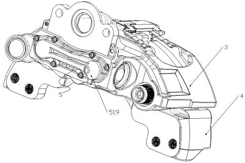
[0055] Such as Figure 1-Figure 10 A pneumatic disc brake shown includes a caliper body 3 , a brake disc 4 and a linkage device 5 .

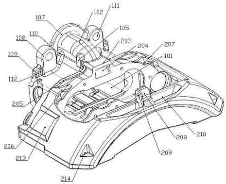
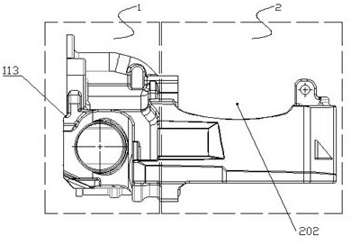
[0056] Such as Figure 2-Figure 7 It can be seen from the schematic diagram shown that the pliers body includes a pliers body body, which is formed by joint connection of the box body section 1 and the bridge section 2, and the connection between the box body section 1 and the bridge section 2 adopts an arc-shaped transition connection , the box section 1 and the bridge section 2 are distributed in a convex shape as a whole.

[0057] The box section 1 has a rectangular shape and has a first installation cavity 101 in the box section 1 to facilitate the installation of the remaining components. There is a first protrusion protruding upward i...


PUM


Abstract

The invention relates to an air disc brake. The air disc brake comprises a caliper body, a brake disc and a linkage device; the caliper body comprises a caliper main body, and the caliper main body isformed by jointly connecting a box body section and a bridge frame section; a first mounting cavity is formed in the box body section, and a first bulge, a driving connecting plate, a second bulge and a connecting hole group are arranged on the box body section; a second bulge, a third bulge, a first groove, a second groove and a fourth bulge are arranged on the bridge frame section; and arc-shaped transition connection is adopted at the joint of the box body section and the bridge frame section. Compared with the prior art, the air disc brake has the advantages that a traditional caliper body structure is improved, on the basis that the overall structural strength of the caliper body is met, the overall size of the caliper body is reduced as much as possible through mutual cooperation ofdifferent structures such as the bulge structure, the arc-shaped section structure, the groove structure and the arc-shaped transition connecting structure, installation of the caliper body is facilitated, and the caliper body is prevented from interfering with the installation of other parts of an automobile.

Description

technical field [0001] The invention relates to an automobile brake, in particular to an air pressure disc brake. Background technique [0002] Disc brakes have been widely used in cars, passenger cars and dangerous goods vehicles. Now most cars are used for all wheels, and a few cars are only used as front wheel brakes, which cooperate with rear wheel drum brakes to make the car have a higher braking force. Directional stability when moving. In commercial vehicles, disc brakes are now gradually being adopted in new and high-end models. [0003] There are air pressure disc brakes, which are controlled by air pressure. The main components include brake discs, air chambers, brake calipers, brackets, etc. The disc brake has fast heat dissipation, light weight, simple structure and convenient adjustment. Especially when the load is high, the high temperature resistance is good, the braking effect is stable, and it is not afraid of muddy water invasion. When driving in winter ...

Claims


Application Information

Patent Timeline
IPC IPC(8): F16D65/00F16D65/095
CPCF16D65/0068F16D65/095
Inventor 毛永锋曹戬刘浩邓晓峰李蒙蒙
Owner JIANGSU CASHIDA TRANSMISSION TECH CO LTD
Learn More