

Differential mechanism of transmission system of automobile
A transmission system and differential technology, applied in the direction of transmission, vehicle parts, differential transmission, etc., can solve the problems of input gear wear, large input gear size, etc., to prolong service life, reduce size, improve height Effect of variable load and shock load capacity
- Summary
- Abstract
- Description
- Claims
- Application Information
AI Technical Summary
Problems solved by technology
Method used
Image

Examples
Embodiment Construction
[0010] The present invention will be described in further detail below in conjunction with the accompanying drawings and specific embodiments.
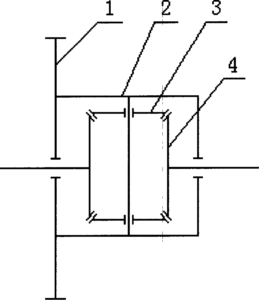
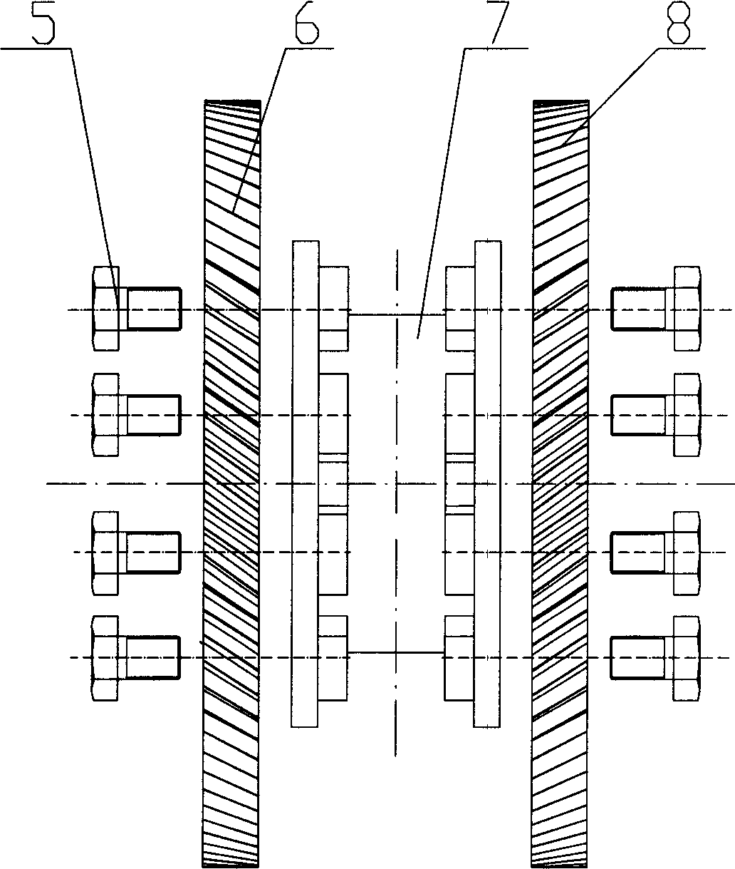
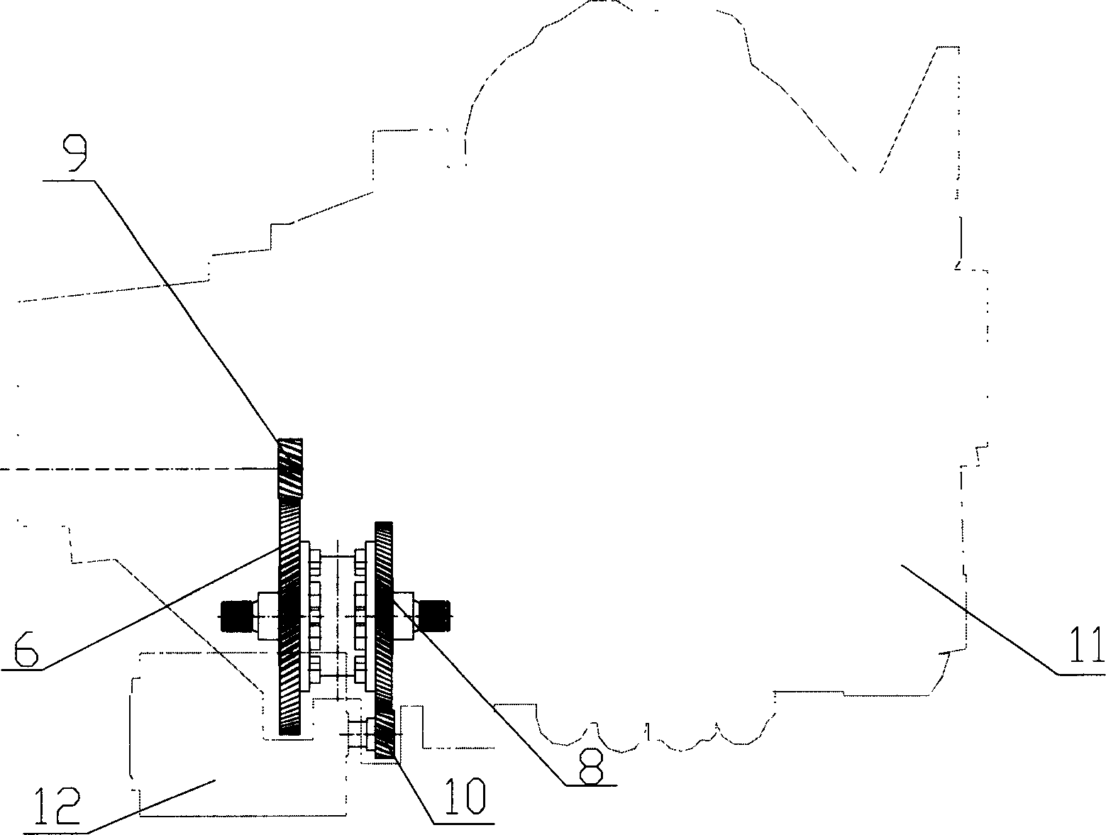
[0011] Such as figure 2 As shown, the differential in the vehicle drive train provided by the present invention includes a planetary assembly 7, the outer shell of the planetary assembly 7 has input gears, and there are multiple input gears, preferably 2-4.
[0012] Wherein, planetary assembly 7 can adopt traditional planetary assembly, also can adopt the planetary assembly disclosed in CN 2644210Y, for example, this planetary assembly can include planetary carrier, planetary wheel and output gear (not shown in the figure) .
[0013] Preferably, the outer shell of the planetary assembly 7 has two input gears 6 , 8 respectively arranged on opposite sides of the outer shell of the planetary assembly 7 . By connecting one input gear 6 to the vehicle engine and the other input gear 8 to the electric motor, a hybrid combined drive can b...
PUM
 Abstract
Description
Claims
Application Information