Valve unit, valve assembly and method for checking closed state of valve unit

A technology of valve unit and valve closing, applied in the direction of parts in contact between valve elements and valve seats, engine elements, valve operation/release devices, etc., can solve problems such as low conductivity and achieve reliable leakage effects

Pending Publication Date: 2020-12-15
BURKERT WERKE
View PDF0 Cites 0 Cited by
  • Summary
  • Abstract
  • Description
  • Claims
  • Application Information

AI Technical Summary

Problems solved by technology

[0004] However, in fluids with low particle concentrations, the known m

Method used


Image

  • Valve unit, valve assembly and method for checking closed state of valve unit
  • Valve unit, valve assembly and method for checking closed state of valve unit
  • Valve unit, valve assembly and method for checking closed state of valve unit

Examples


Embodiment Construction

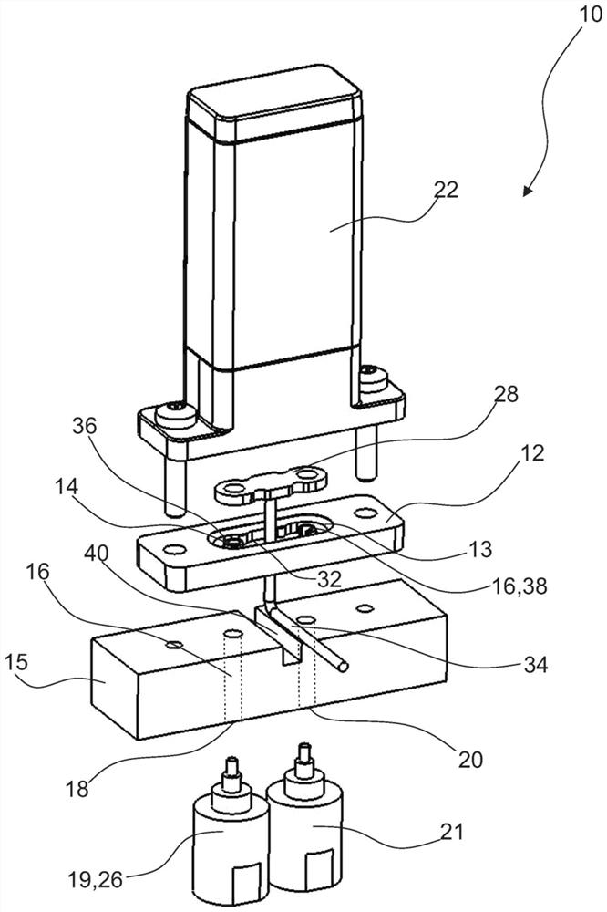
[0039] figure 1 A valve unit for metering fluids such as medical reagents is shown in an exploded view.

[0040] The valve unit 10 comprises a fluid housing 12 which has a valve seat 14 . The valve seat 14 is preferably integrally formed in the fluid housing 12 .

[0041] In particular, the valve seat 14 is arranged in a recess 13 in the fluid housing 12 .

[0042] The section of the fluid channel 16 runs in the fluid housing 12 from the fluid inlet 18 to the valve seat 14 and from there to the fluid outlet 20 .

[0043] exist figure 1 In the valve unit 10 illustrated in , the fluid housing 12 is arranged on an additional flange housing 15 . The fluid channel 16 continues in the flange housing 15 such that a fluid inlet 18 and a fluid outlet 20 are located on the flange housing 15 .

[0044] exist figure 1In the embodiment shown in , a flanged housing 15 for the valve unit 10 is shown. In practice, however, several valve units 10 are often required in a metering process...


PUM


Abstract

The invention relates to a valve unit (10) for metering a fluid, comprising: a fluid housing (12) having a valve seat (14); a fluid passage (16) extending from the fluid inlet (18) to the valve seat (14) and from the valve seat to the fluid outlet (20); a movably mounted valve closing body (24) for controlling or regulating the flow through the fluid channel (16); a first electrode (26) and a second electrode (28), the first electrode (26) being arranged upstream of the valve seat (14) in the fluid channel (16) and the second electrode (26) being arranged downstream of the valve seat (14) in the fluid channel (16), the maximum distance between the two electrodes (26, 28) being 3 mm and/or the maximum distance between each electrode (26, 28) and the valve seat being 1.5 mm. The invention further relates to a valve assembly (50) and to a method for checking the closed state of a valve unit (10).

Description

technical field [0001] The invention relates to a valve unit for metering fluids, a valve assembly with the valve unit and a method for checking the closed state of the valve unit. Background technique [0002] Reliable closing of the valve unit is particularly important in sensitive areas where expensive reagents are often used, for example when metering fluids in medical technology. Significant damage can occur due to a leaky, dripping valve unit, for example if reagents flow out or become contaminated due to a leaky valve unit. Therefore, it is very important to be able to identify a leak. [0003] When metering fluids with a sufficiently high ion concentration, leaks can be determined from the conductivity of the fluid. [0004] However, in fluids with a low particle concentration, known measuring methods do not work due to the low electrical conductivity of the fluid. Contents of the invention [0005] It is therefore an object of the present invention to ensure a ...

Claims


Application Information

Patent Timeline
IPC IPC(8): F16K37/00G01M3/18
CPCF16K37/005G01M3/184F16K31/0655F16K37/0041F16K21/16F16K25/005F16K1/427F16K1/36
Inventor 托马斯·黑恩弗洛里安·菲舍尔
Owner BURKERT WERKE
Why Eureka
Try Eureka