Condenser microphone and output connector therefor

a condenser microphone and output connector technology, applied in the direction of piezoelectric/electrostrictive transducers, coupling device connections, transducer types, etc., can solve the problem of sometimes generated nois

Inactive Publication Date: 2013-04-23
AUDIO-TECHNICA
View PDF2 Cites 0 Cited by
  • Summary
  • Abstract
  • Description
  • Claims
  • Application Information

AI Technical Summary

Benefits of technology

[0025]According to the present invention, on the base inner surface side located on the inside of the microphone casing of the connector base, the circuit board mounted with the capacitor element for high-frequency current bypass connected between the first pin and the second and third pins is arranged, and on the outer surface and / or the inner surface of the shield cover provided so as to cover the whole surface of the circuit board, the magnetic sheet preferably made of a non-conducting and flexible sheet material containing magnetic powder in a resin is further provided additionally so as to be stuck fast to the peripheries of the pins. Thereby, the leak of a high-frequency magnetic field, which is generated by the flow of a high-frequency current in the capacitor element for high-frequency current bypass, into the microphone casing can be prevented reliably. Therefore, an output connector for a condenser microphone which has a function of shielding electromagnetic waves more reliably, and a condenser microphone having this output connector are provided.

Problems solved by technology

However, by a leaking high-frequency magnetic field, a high-frequency current is caused to flow by induction in the pattern of printed wiring board for outputting sound signals and the circuit parts mounted thereon in the microphone casing, and thereby noise is sometimes generated.

Method used


Image

  • Condenser microphone and output connector therefor
  • Condenser microphone and output connector therefor
  • Condenser microphone and output connector therefor

Examples


Embodiment Construction

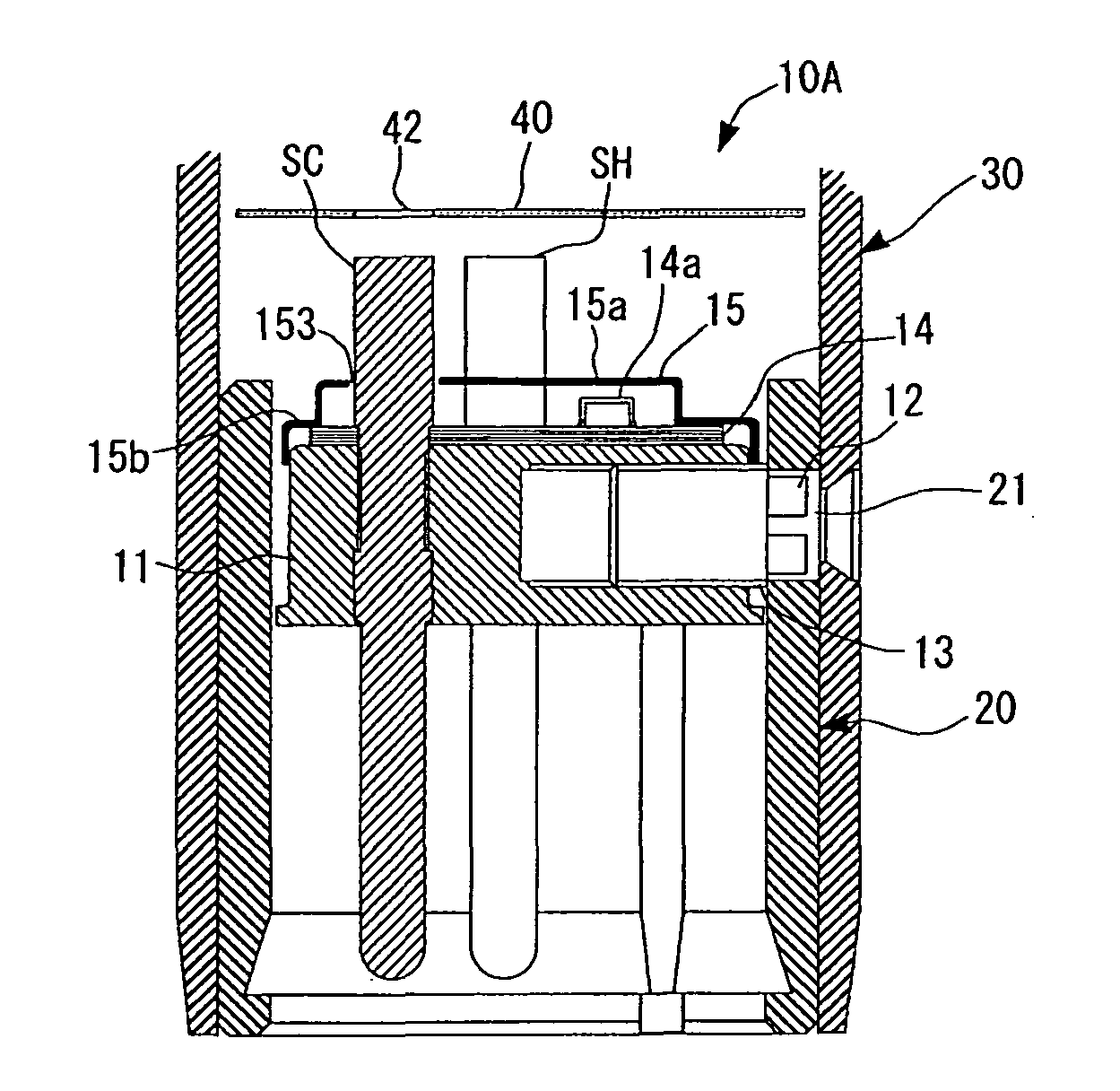
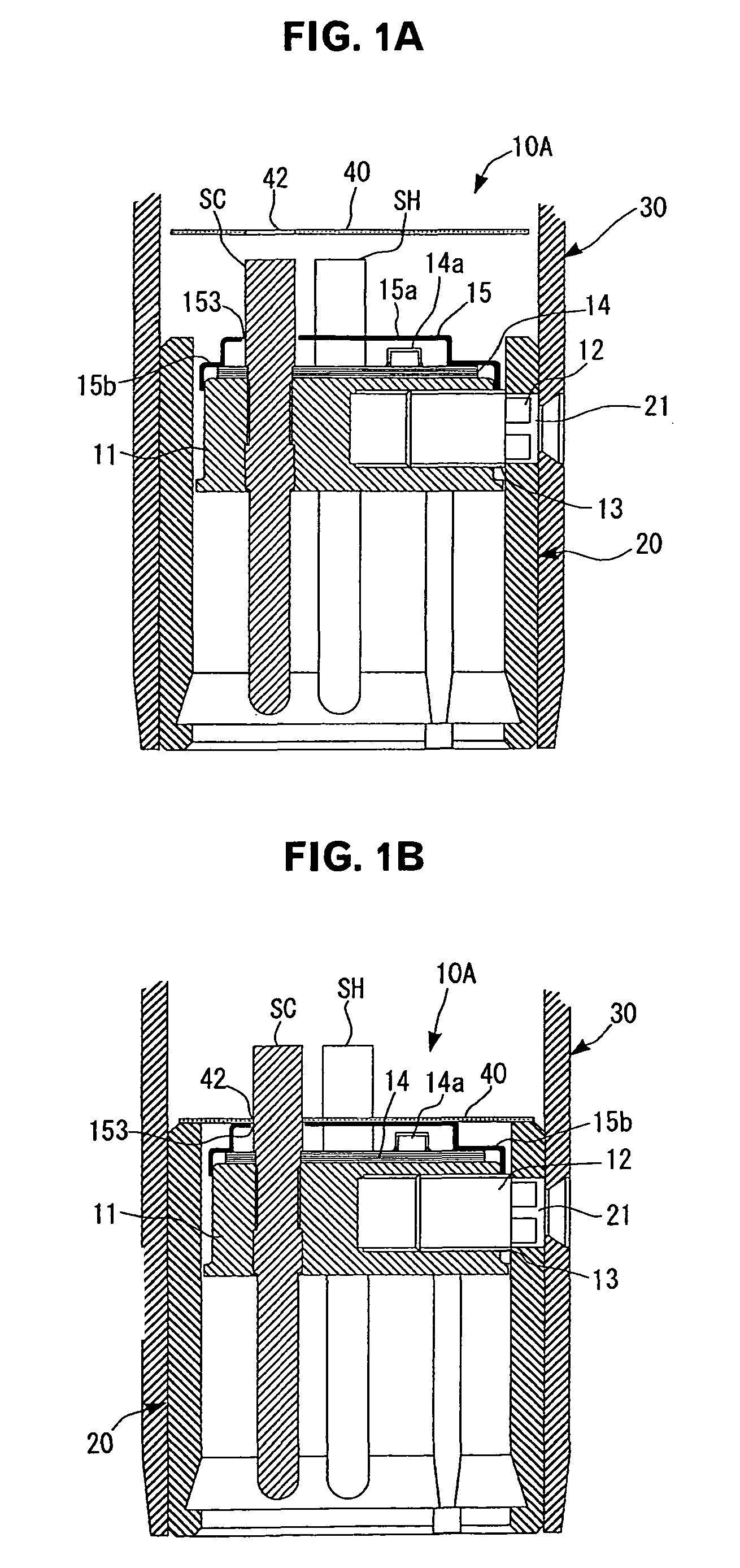
[0033]An embodiment of the present invention will now be described with reference to FIGS. 1A, 1B, 2A and 2B. The present invention is not limited to the embodiment described below. This embodiment is explained by applying the same reference symbols to elements that need not be changed from the elements of the conventional example explained before with reference to FIGS. 3A to 3C.

[0034]Referring to FIGS. 1A and 1B, an output connector 10A in accordance with this embodiment also includes a disc-shaped connector base 11 consisting of an electrical insulator such as PBT (polybutylene terephthalate) resin.

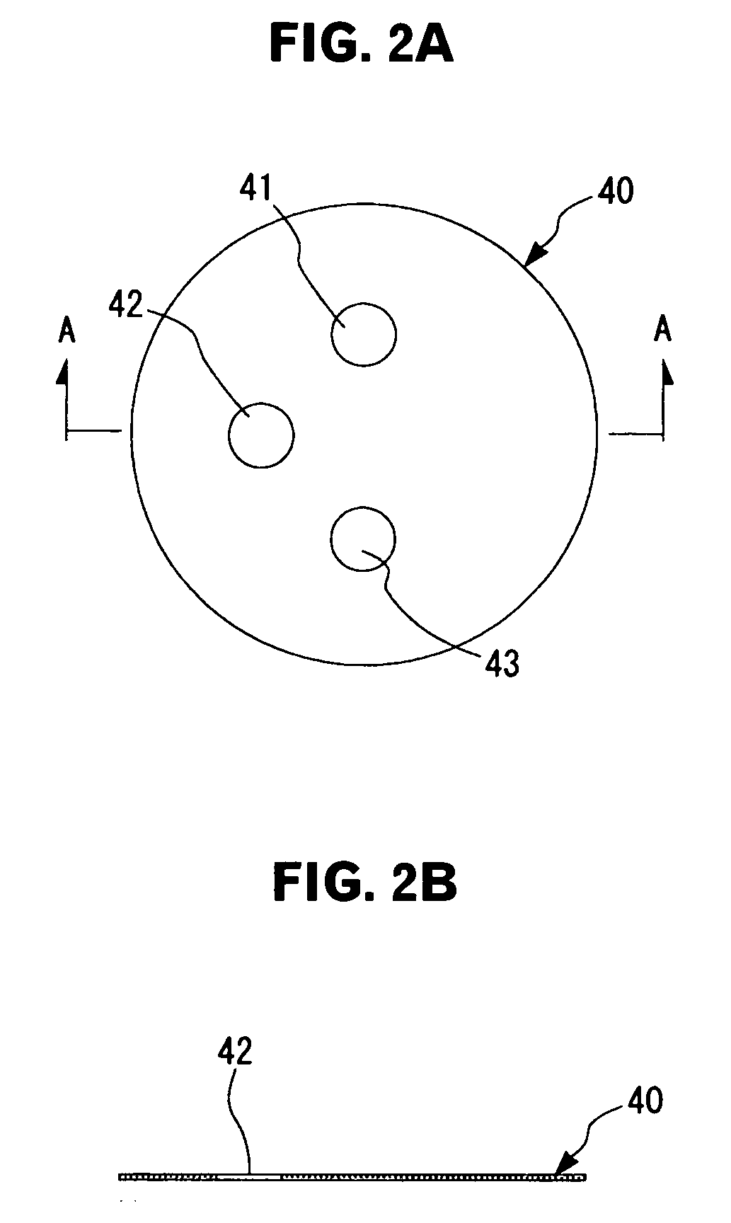
[0035]In the connector base 11, three pins of a first pin E for earthing (an earthing pin E), a second pin SH on the hot side of signal (a signal pin SH), and a third pin SC on the cold side of signal (a signal pin SC) are penetratingly provided, for example, by press fit.

[0036]In the connector base 11, an internally threaded hole 13 is formed toward the radial direction from the outer...


PUM


Abstract

The output connector for a condenser microphone has a circuit board mounted with a capacitor element and a shield cover having a first through hole, a second through hole, and a third through hole and covering the whole surface of the circuit board arranged in a state in which a first pin, a second pin, and a third pin are inserted through the first through hole, the second through hole, and the third through hole respectively, and the shield cover has a non-conducting magnetic sheet having a first insertion hole, a second insertion hole, and a third insertion hole through which the first pin, the second pin, and the third pin are also inserted respectively, on at least one of an outer surface and an inner surface of the shield cover.

Description

CROSS-REFERENCE TO RELATED APPLICATION[0001]The present application is based on, and claims priority from, Japanese Application Serial Number JP2010-067711, filed Mar. 24, 2010, the disclosure of which is hereby incorporated by reference herein in its entirety.TECHNICAL FIELD[0002]The present invention relates to an output connector for a condenser microphone. More particularly, it relates to an output connector for a microphone which has a function of shielding high-frequency electromagnetic waves radiated from a cellular phone or the like, and a condenser microphone provided with the said output connector.BACKGROUND ART[0003]A condenser microphone is configured so that an electrostatic acousto-electric converter in which a diaphragm and a backplate are arranged opposedly is included in a microphone unit, and an impedance converter such as a field effect transistor (FET) is incorporated because of its very high impedance. Usually, in the condenser microphone, a phantom power source...

Claims


Application Information

Patent Timeline
Patent Type & Authority Patents(United States)
IPC IPC(8): H04R25/00
CPCH01R13/719H01R13/6658H01R2103/00
Inventor AKINO, HIROSHI
Owner AUDIO-TECHNICA
Why Eureka
Try Eureka