Anti-dislocation assembly tool for rearview mirror
A technology for assembling tooling and rearview mirrors, which is applied in the direction of manufacturing tools and hand-held tools, etc. It can solve the problems of no locking structure, low assembly efficiency, and inconvenient use by operators, so as to achieve reasonable structural design, improve assembly efficiency, and facilitate assembly Effect
- Summary
- Abstract
- Description
- Claims
- Application Information
AI Technical Summary
Problems solved by technology
Method used
Image

Examples
Embodiment 1
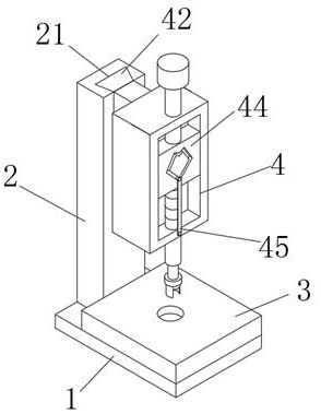
[0033] Refer to attached Figure 1-3 , a rearview mirror anti-displacement assembly tooling, including a base 1, a stand 2 and a pallet 3 arranged on the base 1, a push structure 4 arranged on the stand 2, and a pressing block 5 connected to the push structure 4, The pushing structure 4 can be locked after being pressed down, and the pushing structure 4 is connected with the driving structure 5 .
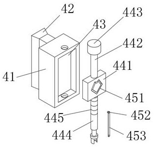
[0034] The pushing structure 4 includes a supporting part 41, and one side of the supporting part 41 is provided with a dovetail slider 42, and one side of the dovetail slider 42 is matched and connected to the dovetail groove 21 arranged on the stand 2, and bolts are used to The dovetail slider 42 is fixed on the stand 2 ; a groove 43 is arranged inside the support member 41 , and a pushing unit 44 is arranged inside the groove 43 .
[0035] The pushing unit 44 includes a moving block 441, which is slidingly connected to the groove 43, and the top of the moving block 441 is provid...
Embodiment 2
[0044] Refer to attached Image 6 , the rope winding wheel 53 is arranged on the side of the pallet 3, the driving column 55 is detachably connected to the sliding block 446, the sliding block 446 is arranged on both sides of the moving block 441, and the supporting member 41 corresponds to The position is provided with sliding groove 41
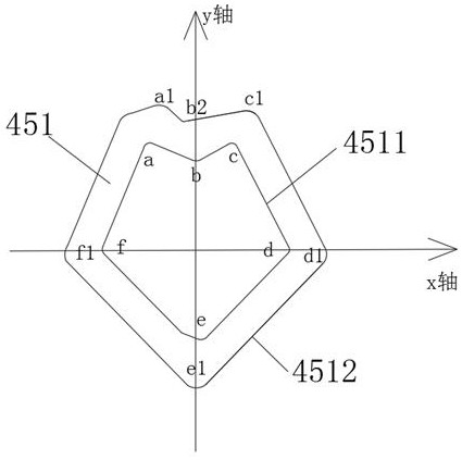
[0045] Working principle of the present invention: the mandrel of the rearview mirror is placed in the placement groove on the supporting plate 2, and the rotating rod 51 is rotated manually or by a motor, so that the winding wheel 53 is rewound with the traction rope 54, and the traction rope 54 pulls the driving column 55, The drive column 55 drives the moving block 441 to move downward, so that the push rod 444 drives the pressing block 6 to press down. Under the special structure of the special-shaped groove 451, the design of pressing down locking and pressing down releasing of the pressing block 6 is realized, and the moving block 441 ...
PUM
 Abstract
Description
Claims
Application Information
 - R&D
- Intellectual Property
- Life Sciences
- Materials
- Tech Scout
- Unparalleled Data Quality
- Higher Quality Content
- 60% Fewer Hallucinations
Browse by: Latest US Patents, China's latest patents, Technical Efficacy Thesaurus, Application Domain, Technology Topic, Popular Technical Reports.
© 2025 PatSnap. All rights reserved.Legal|Privacy policy|Modern Slavery Act Transparency Statement|Sitemap|About US| Contact US: help@patsnap.com