Anti-seepage water stop structure on water conservancy project

A water conservancy project and water-stop technology, which is applied in the field of anti-seepage and water-proof structures, can solve the problems of inconvenient maintenance of the filter plate and the inability of the water-stop plate to discharge water in time, and achieve the effects of easy cleaning, water discharge, and water leakage

Active Publication Date: 2020-12-18
何铁柱
View PDF10 Cites 0 Cited by
  • Summary
  • Abstract
  • Description
  • Claims
  • Application Information

AI Technical Summary

Problems solved by technology

[0004] The purpose of the present invention is to provide an anti-seepage and water-proof structure in hydraulic engineering to solve the problem that the filte

Method used


Image

  • Anti-seepage water stop structure on water conservancy project
  • Anti-seepage water stop structure on water conservancy project
  • Anti-seepage water stop structure on water conservancy project

Examples


no. 1 example

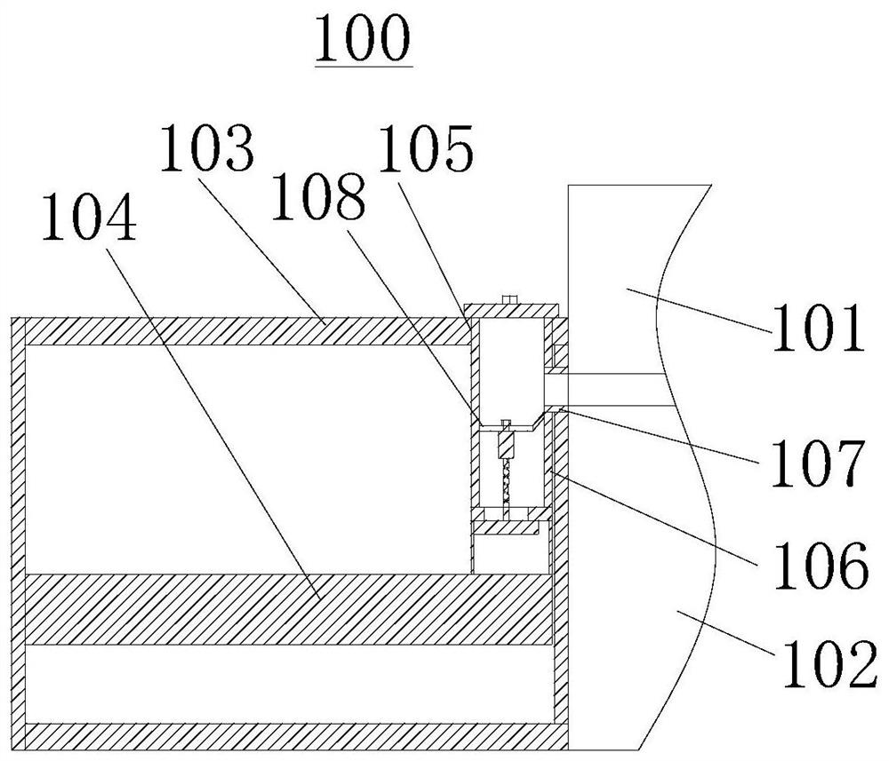
[0039] Please refer to Figure 1-5 , the present embodiment provides an anti-seepage and water-proof structure 100 in hydraulic engineering, which can ensure that the filter plate 108 is unblocked in real time during the working process, and at the same time, the water-stop plate 115 is vertically arranged to facilitate water discharge, so it has overall Strong industrial applicability and practicality.

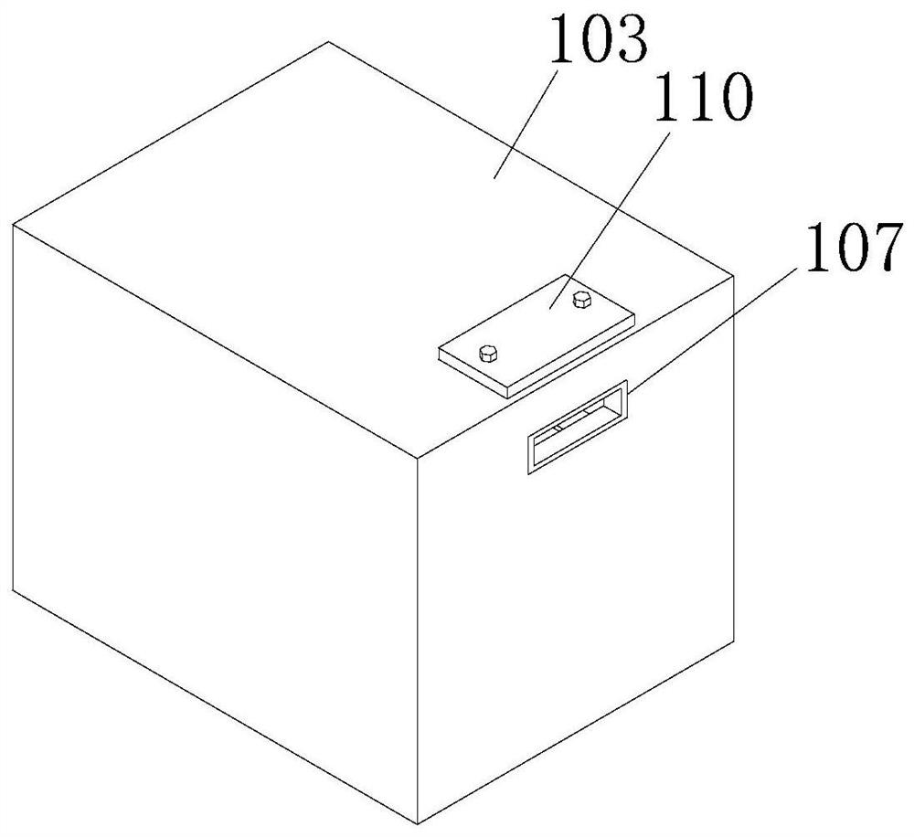
[0040] Further specifically, the anti-seepage and water-proof structure 100 provided in this embodiment includes a concrete layer 101, the bottom side of the concrete layer 101 is fixedly installed with a waterproof board 102 for waterproofing, and the concrete layer 101 and the waterproof board 102 The same water tank 103 is fixedly installed on one side, and a material box 104 is arranged in the water tank 103 .

[0041]Further, a jack 105 is provided on the water tank 103, and a filter box 106 is plugged into the jack 105. The bottom side of the filter box 106 is in conta...

no. 2 example

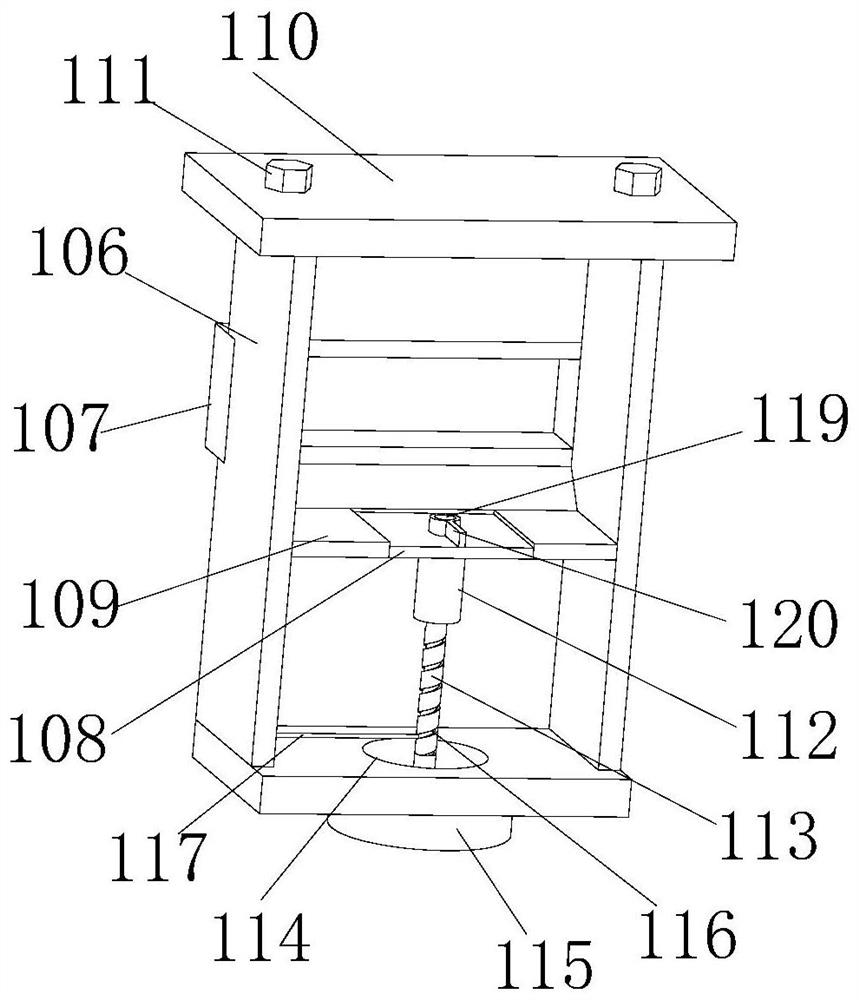
[0059] Please refer to Figure 6-7 and in the first example Figure 1-5 , this embodiment provides an anti-seepage and water-proof structure 200 on hydraulic engineering, which is roughly the same as the anti-seepage and water-proof structure 100 on hydraulic engineering provided in the first embodiment, the difference is that the cleaning structure in this embodiment Component 220 is different.

[0060] Specifically, in the anti-seepage and water-proof structure 200 of the water conservancy project in this embodiment, three sets of cleaning structure assemblies 220 are provided, and the three sets of cleaning structure assemblies 220 are arranged around the circumferential array of the rotating rod 119 . It should be noted that such a setting is to speed up the cleaning efficiency of the cleaning structural assembly 220 and reduce the workload of a single cleaning structural assembly 220, so that the use of a single cleaning structural assembly 220 can be extended while impr...


PUM


Abstract

The invention provides an anti-seepage water stop structure on a water conservancy project, and relates to the field of water conservancy projects. The anti-seepage water stop structure comprises a concrete layer, wherein a waterproof plate is fixedly installed on the bottom side of the concrete layer, a same water tank is fixedly installed on one side of the concrete layer and one side of the waterproof plate, a material box is arranged in the water tank, an inserting hole is formed in the water tank, a filter box is inserted into the inserting hole, the bottom side of the filter box is in contact with the material box, and a flow guide plate is fixedly installed in the filter box. According to the anti-seepage water stop structure, a pull rod and a cleaning structure assembly are arranged, so that a cleaning rod cleans the top side of a filter plate through a plurality of brushes, and then the smoothness of the filter plate is guaranteed; meanwhile, a water stop plate is vertically arranged, so that water outlet is facilitated; and in addition, the filter box and a cover plate are arranged, when a large amount of silt is accumulated in the filter box, the filter box can be pulledout by pulling the cover plate, then two bolts are disassembled, then the cover plate can be taken down, so that the silt in the filter box can be conveniently cleaned, and the use of the filter boxis more convenient.

Description

technical field [0001] The invention relates to the technical field of water conservancy engineering, in particular to an anti-seepage and water-proof structure in water conservancy engineering. Background technique [0002] Water is the basic element for human survival, and electricity is the main energy source for social development. The discipline of water conservancy and hydropower engineering is an engineering science that regulates and utilizes water energy resources by engineering or non-engineering measures on the basis of the study of the natural characteristics of water. In the field of water conservancy engineering, anti-seepage and water-proof structures are often required. [0003] In the prior art, the patent whose publication number is CN208563260U discloses a kind of anti-seepage and water-proof structure used in water conservancy and hydropower projects, which realizes the collection of water and purifies the water at the same time, so this kind of structure...

Claims


Application Information

Patent Timeline
IPC IPC(8): E02B3/16B01D29/03B01D29/64B01D29/96
CPCE02B3/16B01D29/03B01D29/6415B01D29/96
Inventor 叶军郑松
Owner 何铁柱
Why Eureka
Try Eureka