Rainwater flow-dividing type drainage device for sponge city construction

A sponge city and drainage device technology, applied in water supply devices, grease/oily substance/float removal devices, buildings, etc., can solve problems such as inability to purify rainwater, blockage of drainage pipes, and backflow of water wells, and improve efficiency and quality. Improves discharge rates and reduces backflow problems

Active Publication Date: 2020-12-18
LIAOCHENG UNIV
View PDF7 Cites 5 Cited by
  • Summary
  • Abstract
  • Description
  • Claims
  • Application Information

AI Technical Summary

Problems solved by technology

[0003] General urban rainwater drainage has failed to solve the problem of rainwater counterflow well. Water wells often have backflow problems, resulting in not only ineffective drainage of road area water, but even traffic accidents caused by rainwater flowing out of wells, and drainage pipes often Blockage occurs, it is difficult to clean up, time-consuming and labor-intensive, the discharged rainwater is relatively turbid, mixed with stones, branches and other debris, cannot fully purify the rainwater, and greatly wastes fresh water resources

Method used


Image

  • Rainwater flow-dividing type drainage device for sponge city construction
  • Rainwater flow-dividing type drainage device for sponge city construction
  • Rainwater flow-dividing type drainage device for sponge city construction

Examples


Embodiment Construction

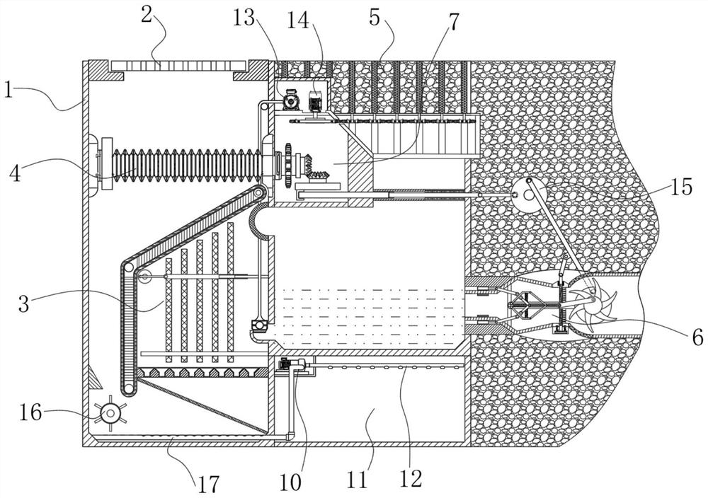
[0034] refer to figure 1 , the present invention provides a technical solution: a rainwater diversion discharge device for sponge city construction, which includes a diversion box shell 1, a diversion filter assembly 3, a sludge chamber 11, a water inlet pipe 5, a transmission box body 7, and a drainage assembly 6. Wherein, a separator is arranged in the middle of the splitter box shell 1 to divide it into a left and a right rainwater treatment structure, a manhole cover 2 is arranged on the upper end of the left part of the diverter box shell 1, and a diversion filter is installed under the manhole cover 2 Component 3, the upper end of the right part of the splitter box shell 1 is provided with a water inlet pipe 5, and a transmission box 7 is installed below the water inlet pipe 5, wherein the transmission box 7 is located on the upper part of the partition;

[0035]The sludge chamber 11 is arranged at the lower end of the right part of the splitter box shell 1, and the drai...


PUM


Abstract

The invention discloses a rainwater flow-dividing type drainage device for sponge city construction. The rainwater flow-dividing type drainage device comprises a flow-dividing box shell, a flow-guiding filtering assembly, a sludge chamber, a water inlet pipe, a transmission box body and a drainage assembly, wherein a partition plate is arranged in the middle of the flow-dividing box shell to divide the flow-dividing box shell into a left rainwater treatment structure and a right rainwater treatment structure; a well lid is arranged at the upper end of the left part of the flow-dividing box shell; the flow-guiding filtering assembly is installed below the well lid; the water inlet pipe is arranged at the upper end of the right part of the flow-dividing box shell; the transmission box body is installed below the water inlet pipe; the sludge chamber is arranged at the lower end of the right part of the flow-dividing box shell; and the drainage assembly is arranged on the right side of theflow-dividing box shell, communicates with the box wall on the right side and relatively located above the sludge chamber.

Description

technical field [0001] The invention relates to the technical field of urban rainwater discharge, in particular to a rainwater diversion discharge device for sponge city construction. Background technique [0002] Sponge city refers to a city that can be like a sponge and has good "elasticity" in adapting to environmental changes and responding to natural disasters. When it rains, it absorbs, stores, infiltrates, and purifies water. use. To maximize the accumulation, infiltration and purification of rainwater in urban areas, and to promote the utilization of rainwater resources and the protection of the ecological environment. In the process of sponge city construction, coordinate water supply, drainage and other water recycling links to maximize the accumulation, infiltration and purification of rainwater in urban areas, and promote the utilization of rainwater resources and ecological environment protection. [0003] General urban rainwater drainage has failed to solve t...

Claims


Application Information

Patent Timeline
Patent Type & Authority Applications(China)
IPC IPC(8): E03F1/00E03F5/00E03F5/14
CPCE03F1/00E03F5/00E03F5/14
Inventor 苏志彬季德垒孙胜男
Owner LIAOCHENG UNIV
Why Eureka
Try Eureka