
Assembled building steel structure composite beam

A technology of steel structure and composite beam, applied in the field of building steel structure, can solve problems such as affecting building construction efficiency and inconvenient assembly, and achieve the effects of convenient operation, convenient disassembly and installation, and easy assembly.

Pending Publication Date: 2020-12-18
宿迁小鲤工业设计有限公司
View PDF16 Cites 0 Cited by
  • Summary
  • Abstract
  • Description
  • Claims
  • Application Information

AI Technical Summary

Problems solved by technology

[0002] Construction engineering refers to engineering entities formed through the construction of various housing buildings and their ancillary facilities and the installation activities of supporting lines, pipelines, and equipment. As well as projects that can form internal spaces to meet the needs of people's production, living, learning, and public activities. In existing construction projects, in order to maintain the stability of buildings, building steel structure composite beams are usually used, but existing buildings During the construction process of steel structure composite beams, there is a problem that it is not easy to assemble, which will affect the overall construction efficiency of the building

Method used


Image

  • Assembled building steel structure composite beam
  • Assembled building steel structure composite beam
  • Assembled building steel structure composite beam

Examples


Embodiment Construction

[0023] The following will clearly and completely describe the technical solutions in the embodiments of the present invention with reference to the accompanying drawings in the embodiments of the present invention. Obviously, the described embodiments are only some, not all, embodiments of the present invention. Based on the embodiments of the present invention, all other embodiments obtained by persons of ordinary skill in the art without making creative efforts belong to the protection scope of the present invention.

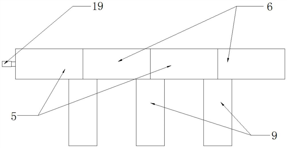
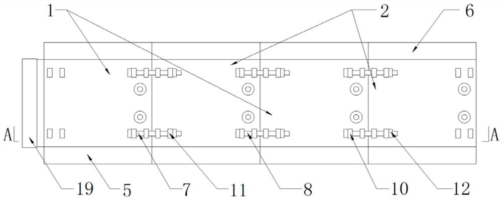
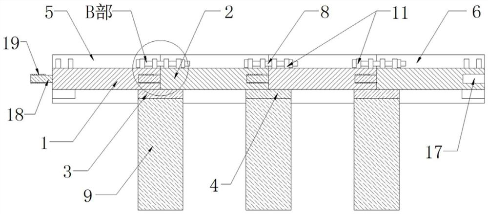
[0024] Such as Figure 1-Figure 7 As shown, this specific embodiment adopts the following technical scheme: it includes No. 1 beam body 1, No. 2 beam body 2, No. 1 connecting plate 3, No. 2 connecting plate 4, No. 1 vertical plate 5, No. No. 1 connecting screw 7 and No. 2 connecting screw 8, several No. 1 beam bodies 1 and several No. 2 beam bodies 2 are alternately arranged, and No. No. 1 connecting plate 3 is arranged on the right side below 1, and the fron...


PUM


Abstract

The invention discloses an assembled building steel structure composite beam, and relates to the technical field of building steel structures. First vertical plates are arranged at the front side andthe rear side of a first beam body, a first connecting plate is arranged at one side of the lower portion of the first beam body, the front side and the rear side of one side of the first connecting plate are arranged in sliding grooves in the inner sides of the first vertical plates at the front side and the rear side in a sliding manner, and a second connecting plate is arranged below the otherside of a second beam body; the front side and the rear side of one side of the second connecting plate are slidably arranged in sliding grooves in the inner sides of second vertical plates at the front side and the rear side in a sliding manner, a supporting column is fixed to the center of the lower surface of the second connecting plate and the center of the lower surface of the first connecting plate, first connecting rings are fixed to the four corners of the upper surface of a first beam body, and first connecting screw rods are inserted into the first connecting rings; and second connecting rings at the two sides are fixed to the four corners of the upper surface of the second beam body, and second connecting screw rods are inserted into the second connecting rings at the other side, so that splicing can be conducted according to the needed length in the using process, in the splicing process, operation is convenient, assembling is easy, and the overall construction efficiency of a building cannot be affected.

Description

technical field [0001] The invention relates to the technical field of building steel structures, in particular to a composite beam for assembling building steel structures. Background technique [0002] Construction engineering refers to engineering entities formed through the construction of various housing buildings and their ancillary facilities and the installation activities of supporting lines, pipelines, and equipment. As well as projects that can form internal spaces to meet the needs of people's production, living, learning, and public activities. In existing construction projects, in order to maintain the stability of buildings, building steel structure composite beams are usually used, but existing buildings During the construction process of steel structure composite beams, there is a problem that it is not easy to assemble, which will affect the overall construction efficiency of the building. Contents of the invention [0003] The object of the present inve...

Claims


Application Information

Patent Timeline
Patent Type & Authority Applications(China)
IPC IPC(8): E04C3/04E04G21/14
CPCE04C3/04E04G21/14
Inventor 谢宏伟
Owner 宿迁小鲤工业设计有限公司
Learn More