Supercharge Your Innovation With Domain-Expert AI Agents!

A limit clamping device for machining center

A machining center and clamping device technology, applied in clamping devices, positioning devices, metal processing, etc., can solve the problem of poor clamping efficiency and positioning accuracy, affecting feeding efficiency and positioning accuracy, and difficulty in meeting the continuous production needs of machining centers, etc. problems, to achieve the effects of reducing life loss, improving positioning accuracy, and compact continuous production requirements

Active Publication Date: 2022-07-12
苏州艾米欧精密机械股份有限公司
View PDF8 Cites 0 Cited by
  • Summary
  • Abstract
  • Description
  • Claims
  • Application Information

AI Technical Summary

Problems solved by technology

The limit clamping of CNC machining center equipment in the prior art generally adopts clamping tooling, especially when the workpiece structure needs to be fixed at multiple points, resulting in poor clamping efficiency and positioning accuracy. The surface of the bar workpiece is reliably clamped. At the same time, when the vertical lifting limit structure is adopted on the conveyor of the machining center, the impact of the lifting impact on the conveyor will easily reduce the life of the conveyor. When the overall length of multiple workpieces is long, especially continuous When processing and loading from the top, it is necessary to repeatedly shift the limit structure to make way for the loading, and the repeated limit positioning will affect the feeding efficiency and the positioning accuracy of batch processing, and it is difficult to meet the compact continuous production requirements of the machining center

Method used


Image

  • A limit clamping device for machining center
  • A limit clamping device for machining center
  • A limit clamping device for machining center

Examples


Embodiment Construction

[0027] The specific embodiments of the present invention will be further described below with reference to the accompanying drawings.

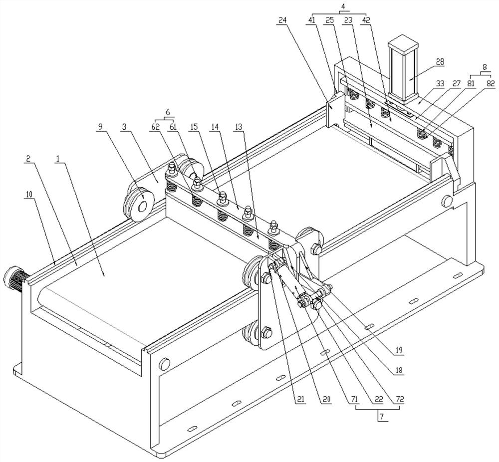
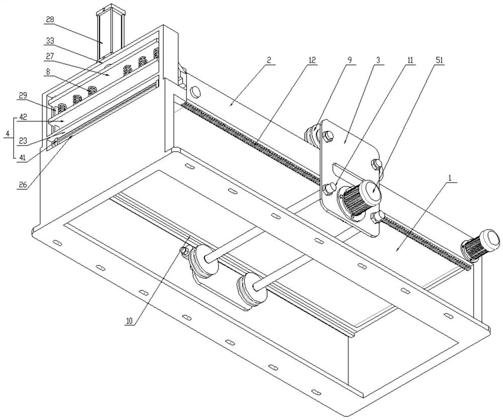
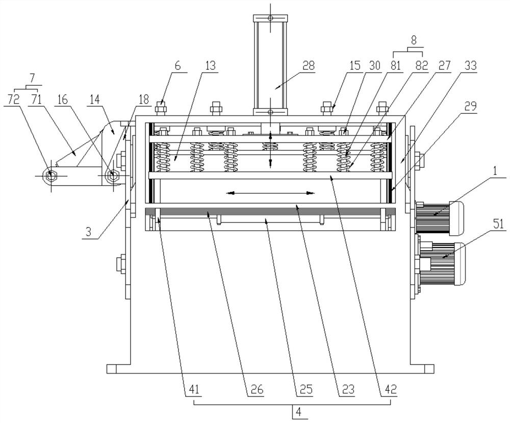
[0028] A limit clamping device for a machining center, comprising a frame 2 outside the conveyor 1 of the machining center, wherein at least one limit frame 3 and a clamping mechanism 4 are arranged on the frame 2, and the limit frame 3. A walking driving mechanism 5 is provided on one side, and the walking driving mechanism 5 is used to drive the limit frame 3 to reciprocate along the parallel direction of the conveyor 1;

[0029] The limit frame 3 includes a first frame plate 31 and a second frame plate 32 located on both sides of the frame 2, and at least one roller 9 is provided on the inner side of the first frame plate 31 and the second frame plate 32. The rack 2 is provided with a raceway 10 parallel to the conveyor 1 and located at the bottom of the rollers 9 or between the corresponding rollers 9 and rolling with the rollers 9. The ro...


PUM


Abstract

The invention relates to a limit clamping device for a machining center, comprising a frame outside the conveyor of the machining center, at least one limit frame and a clamping mechanism are arranged on the frame, and one side of the limit frame is provided with a drive limit The rack moves back and forth along the parallel direction of the conveyor and travels the drive mechanism. The top of the limit plate of the limit rack is provided with a drive plate, and a deflection shaft and a deflection mechanism are arranged between the drive plate and the other side of the limit rack. The deflection mechanism is used to drive the drive The plate is deflected back and forth around the deflection axis. The clamping mechanism includes two first clamping plates that move oppositely along the vertical conveying direction of the conveyor and a second clamping plate that moves relative to the fixed platform. Deflection to realize the side opening and closing of the limit plate on the top of the conveyor, which is convenient for top feeding to avoid repeated positioning, and multi-faceted limit clamping with the clamping mechanism in the lateral and vertical directions to realize workpiece clamping, which is beneficial to improve positioning accuracy. , clamping efficiency and reliability to meet the compact continuous production needs of machining centers.

Description

technical field [0001] The invention relates to a limit clamping device for a machining center, which belongs to the technical field of numerical control machining center equipment. Background technique [0002] The high-efficiency automatic CNC machining center composed of mechanical equipment and CNC system is suitable for processing complex parts. It has the characteristics of high machining accuracy and batch processing efficiency. It is widely used in milling, boring, drilling, sawing and other processing procedures. The conveyor of the machine tool involves a limit clamping device, which is used to limit and clamp one or more workpieces to control the machining position and prevent the workpiece from shaking during the machining process and affecting the machining accuracy. The limit clamping of CNC machining center equipment in the prior art generally adopts clamping tooling, especially when the workpiece structure needs to be fixed at multiple points, resulting in po...

Claims


Application Information

Patent Timeline
Patent Type & Authority Patents(China)
IPC IPC(8): B23Q3/00B23Q7/00
CPCB23Q3/00B23Q7/00B23Q2703/04
Inventor 赵海军
Owner 苏州艾米欧精密机械股份有限公司
Features
  • R&D
  • Intellectual Property
  • Life Sciences
  • Materials
  • Tech Scout
  • Unparalleled Data Quality
  • Higher Quality Content
  • 60% Fewer Hallucinations
Learn More