Automatic adjustable interior decoration spraying device

A technology of spraying equipment and interior decoration, which is applied in the direction of construction and building construction, and can solve problems such as unevenness of the cement layer

Inactive Publication Date: 2020-12-22
广州畅新生物科技有限公司
View PDF5 Cites 0 Cited by
  • Summary
  • Abstract
  • Description
  • Claims
  • Application Information

AI Technical Summary

Problems solved by technology

[0003] Because the feeding hopper of the automatic adjustable interior decoration mortar spraying machine is often open to the outside world for better feeding, so that the upper layer of the cement mortar will be in full contact with the air, if the spraying machine has not finished spraying the cement mortar due to w

Method used


Image

  • Automatic adjustable interior decoration spraying device
  • Automatic adjustable interior decoration spraying device
  • Automatic adjustable interior decoration spraying device

Examples


Embodiment 1

[0026] For example figure 1 -example Figure 5 Shown:

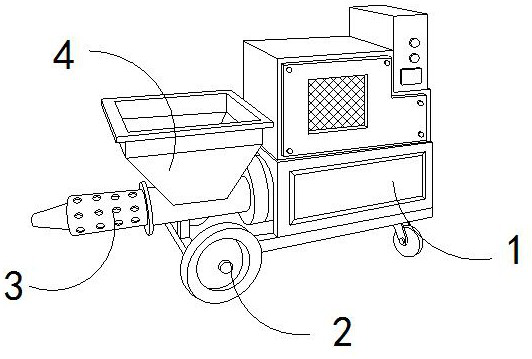
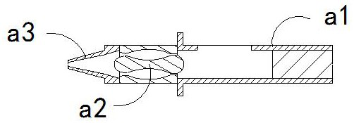
[0027] The present invention provides an automatic and adjustable indoor decoration spraying equipment, the structure of which includes a machine body 1, a moving wheel 2, a discharge pipe 3, and a hopper 4, the moving wheel 2 is engaged with the side of the body 1, and the The feeding hopper 4 is embedded in the upper end of the discharge pipe 3, and the discharge pipe 3 is installed at the front end of the body 1; the discharge pipe 3 includes an outer pipe a1, a separation mechanism a2, and a nozzle a3, and the separation mechanism a2 is embedded in the inner part of the outer tube a1 near the front end, and the spray head a3 and the outer tube a1 are of an integrated structure.

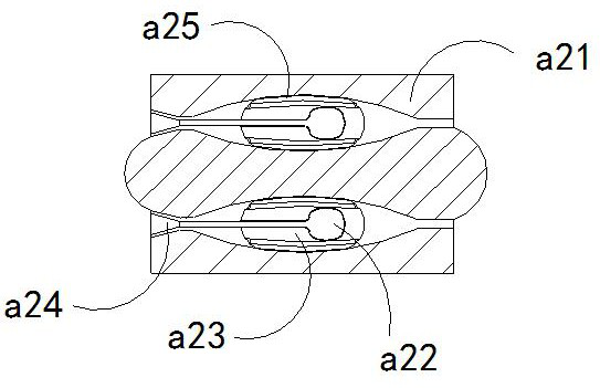
[0028] Wherein, the separation mechanism a2 includes a frame body a21, a rotating shaft a22, a force-bearing plate a23, a fixed seat a24, and a rolling plate a25. The rotating shaft a22 is embedded in the right side of the fixed seat a24, a...

Embodiment 2

[0034] For example Image 6 -example Figure 8 Shown:

[0035] Wherein, the fixed seat a24 includes a swing plate c1, a middle solid plate c2, and an elastic piece c3, the swing plate c1 is hingedly connected to the side of the middle solid plate c2, and the elastic piece c3 is embedded and fixed on the inner side of the swing plate c1 Between the solid plate c2 and the solid plate c2, there are two swing plates c1, which are evenly distributed symmetrically on the upper and lower sides of the solid plate c2. The cement mortar generates an outward thrust on the swing plate c1, which can make the swing The plate c1 swings downward along the solid plate c2, so that the cement mortar can be discharged through the gap between the swinging plate c1 and the inner wall of the object.

[0036] Wherein, the oscillating plate c1 includes an overhanging bar c11, a receiving plate c12, a bottom plate c13, and an elastic bar c14, the outlining bar c11 is movably engaged with the receiving ...


PUM


Abstract

The invention discloses an automatic adjustable interior decoration spraying device. The automatic adjustable interior decoration spraying device structurally comprises a machine body, moving wheels,a discharging pipe and a feeding hopper, wherein the moving wheels are movably clamped to the side of the machine body; the feeding hopper is fixedly embedded in the upper end of the discharging pipe;the discharging pipe is mounted at the front end of the machine body; cement mortar entering the discharging pipe through the feeding hopper generates outward thrust on a separation mechanism, the separation mechanism can guide in non-solidified fluid cement mortar inwards firstly, and thus a rolling plate can roll the cement mortar squeezed between the rolling plate and the inner wall of a frame; through the throwing force generated by upward swinging and resetting of a swinging plate, an outward extending strip can stretch out upwards along a bearing plate to be inserted into the cement mortar; and when the outward extending strip completely contracts, a hollow groove can be reserved in the cement mortar, thus the surface wall of the solidified cement mortar can be thinned, and the solidified thin-wall cement mortar can be broken through by the cement mortar sprayed out next time.

Description

technical field [0001] The invention relates to the field of interior decoration, in particular to an automatic and adjustable interior decoration spraying equipment. Background technique [0002] The automatic adjustable interior decoration mortar spraying machine is mainly used for uniform spraying of cement mortar for interior decoration. By pouring the stirred cement mortar into the hopper, the cement mortar in the hopper is poured into the hopper through the action of the air pump. The mortar is sprayed at high speed from the hose connected to the discharge pipe, so that the cement mortar can be evenly sprayed on the surface of the wall. Based on the above description, the inventor found that the existing automatic adjustable interior decoration spraying equipment mainly exists The following deficiencies, for example: [0003] Because the feeding hopper of the automatic adjustable interior decoration mortar spraying machine is often open to the outside world for better...

Claims


Application Information

Patent Timeline
IPC IPC(8): E04F21/08E04F21/02
CPCE04F21/02E04F21/08
Inventor 杨丽英
Owner 广州畅新生物科技有限公司
Why Eureka
Try Eureka