Moving target time reversal target detection method based on array antenna

A time-reversal and target detection technology, applied in the radar field, can solve the problems of not considering array antenna target detection, low detection result accuracy, and low radar detection performance, so as to improve target detection probability and echo signal-to-noise than the effect

Inactive Publication Date: 2020-12-22
XIDIAN UNIV
View PDF5 Cites 0 Cited by
  • Summary
  • Abstract
  • Description
  • Claims
  • Application Information

AI Technical Summary

Problems solved by technology

Existing studies have shown that for single-antenna radars, time-reversal detectors can effectively detect moving targets, but in a multipath environment, there are few studies on using time-reversal technology to detect moving targets with array antennas. The detection of moving targets based on the antenna radar does not consider how to detect targets based on the array antenna. The detection performance of the radar is low, and the accuracy of the detection results is low.

Method used


Image

  • Moving target time reversal target detection method based on array antenna
  • Moving target time reversal target detection method based on array antenna
  • Moving target time reversal target detection method based on array antenna

Examples


Embodiment 1

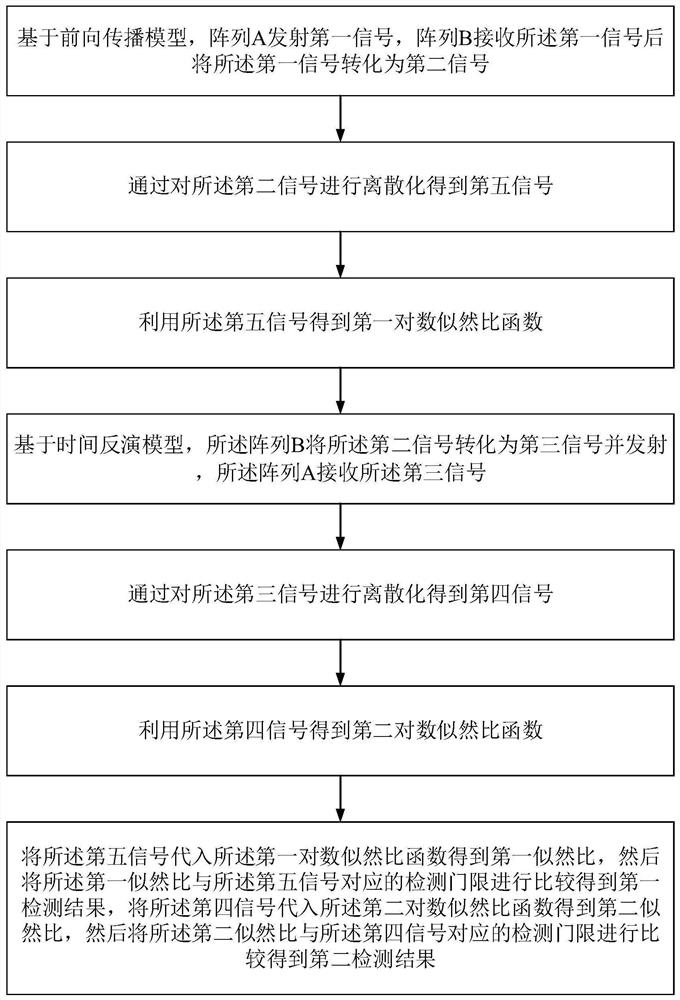
[0042]Seefigure 1 ,figure 1 It is a flowchart of a moving target time-reversal target detection method based on an array antenna provided by an embodiment of the present invention. An array antenna-based time-reversal target detection method for moving targets includes:

[0043]Step 1. Based on the forward propagation model, the array A transmits a first signal, and the array B receives the first signal and converts the first signal into a second signal.

[0044]Further, the array B obtains the second signal by performing convolution and accumulation operations on the first signal and the channel response.

[0045]Specifically, the forward propagation model is first constructed. The forward propagation model is a traditional detection model. The first signal is the emission signal of the m-th element of the array A, denoted as sm(t), the second signal is the received signal of the nth element of the array B, expressed as xn(t), the second signal xnThe expression of (t) is:

[0046]

[0047]Where x...

Embodiment 2

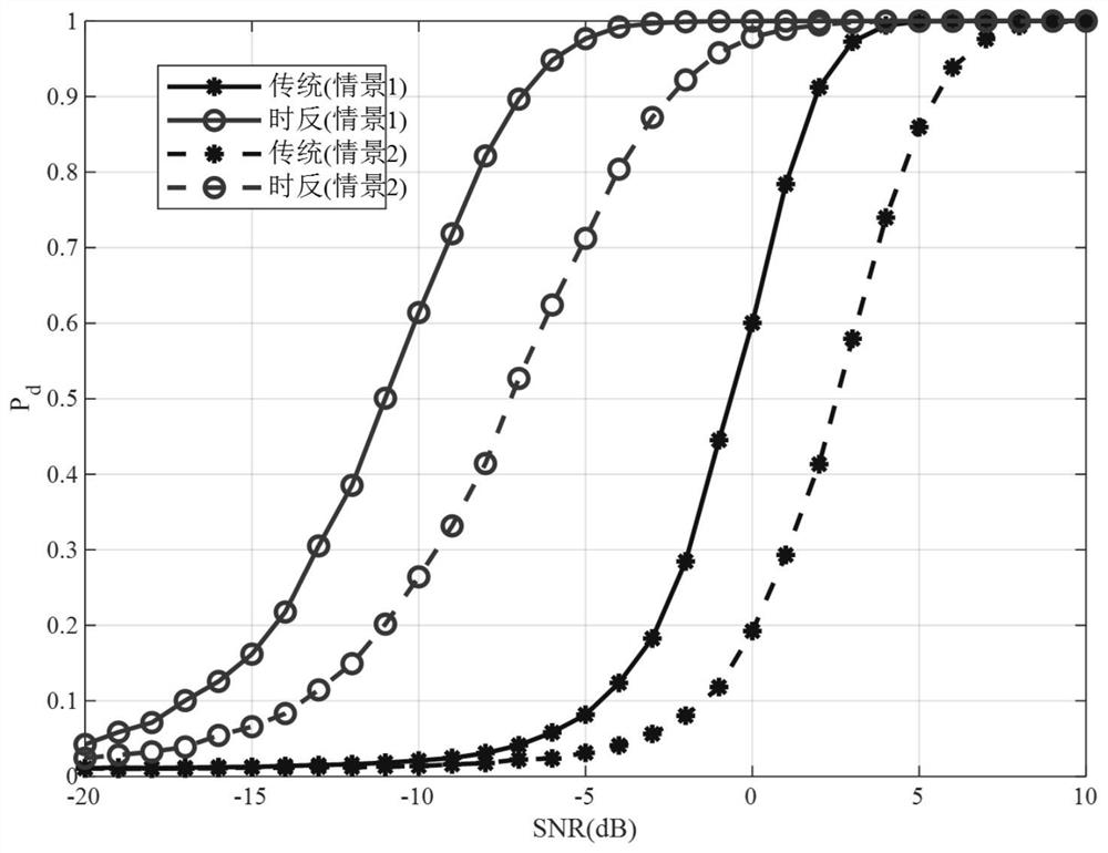
[0103]The effect of the present invention can be verified by the following simulation.

[0104]Simulation conditions:

[0105]The transmitted signal is a chirp signal with a bandwidth of 20MHz and a time width of 5μs. The simulation is carried out on the situation of two different paths of forward propagation and backward propagation. The data processing of the experiment is completed on MATLAB2016, and the channel response of the target is simulated on FEKO.

[0106]Simulation content:

[0107]referencefigure 2 ,figure 2 It is a simulation diagram of the detection probability of a moving target time-reversal target detection method based on an array antenna provided by an embodiment of the present invention.

[0108]Simulation 1, noise varianceThe false alarm probability is 0.01. In the case of many propagation paths, 100,000 Monte Carlo experiments are performed to obtain the detection probability.

[0109]Simulation 2, noise varianceThe false alarm probability is 0.01. In the case of less propagat...


PUM


Abstract

The invention discloses a moving target time reversal target detection method based on an array antenna, and the method comprises the steps: an array A transmits a first signal based on a forward propagation model, an array B receives and converts the first signal into a second signal, discretizes the second signal to obtain a fifth signal, and obtains a first log-likelihood ratio function throughthe fifth signal; based on a time reversal model, the array B converts the second signal into a third signal and transmits the third signal to the array A, discretization is carried out on the thirdsignal to obtain a fourth signal, and the fourth signal is utilized to obtain a second log-likelihood ratio function; and the fifth signal is substituted into the first log-likelihood ratio function to obtain a first likelihood ratio, the first likelihood ratio is compared with a detection threshold to obtain a first detection result, the fourth signal is substituted into the second log-likelihoodratio function to obtain a second likelihood ratio, and the second likelihood ratio is compared with the detection threshold to obtain a second detection result. The detection method provided by theinvention can improve the target detection performance in a multipath effect environment.

Description

Technical field[0001]The invention belongs to the technical field of radars, and specifically relates to a moving target time inversion target detection method based on an array antenna.Background technique[0002]Target detection is one of the important functions of radar. There are usually serious multipath effects in low elevation angle, indoor and urban target detection, which will greatly reduce the detection performance of radar. Time reversal technology uses multipath effects to effectively improve the detection performance of radars, and plays an important role in dense multipath channels. Time reversal technology realizes space-time focusing by reversing the received signal in the time domain and retransmitting to the same channel environment. Therefore, the important premise of time reversal is channel invariance, which ensures that the retransmitted signal is focused on the target .[0003]At present, most of the existing time-reversal target detection algorithms are based on...

Claims


Application Information

Patent Timeline
Patent Type & Authority Applications(China)
IPC IPC(8): G01S13/02G01S7/41
CPCG01S13/02G01S7/41
Inventor 杨明磊连昊张钊铭陈伯孝
Owner XIDIAN UNIV
Why Eureka
Try Eureka