Unified direct-current coding method for position, speed, time and attitude information

A technology of posture information and coding method, which is applied in the field of communication, can solve problems such as difficult integration of interface circuits, heavy interface debugging workload, and many system communication lines, and achieve the effects of reducing workload, simplifying types, and realizing clock synchronization

Pending Publication Date: 2020-12-22
HENAN POLYTECHNIC
4 Cites 0 Cited by

AI-Extracted Technical Summary

Problems solved by technology

[0005] The present invention aims at the transmission of position, speed, time and attitude information by adopting the traditional information transmission method, which requires more data interface types and corresponding driver programs, which will cause many system communication lines, poor reliability, and interface debugging workload Large size, t...

Method used

...

Abstract

The invention belongs to the technical field of communication, and discloses an unified direct-current coding method for position, speed, time and attitude information. The method comprises the following steps of: designing a unified direct-current code PVTA for position, speed, time and attitude, including design of a PVTA data frame structure, definition of a code element waveform, design of a data transmission mode and provision of a time reference mark; uniformly coding time, position, speed and attitude information by adopting a direct current code format based on the designed PVTA code,and conducting synchronous transmission of the time, position, speed and attitude information. According to the invention, organic combination of position, speed, time and attitude information is realized, transmission of the four kinds of information including the time, position, speed and attitude information can be realized only by one data interface, so the types and the number of the data interfaces are greatly reduced, and the structure of hardware equipment is simplified.

Application Domain

Synchronous motors for clocksSynchronisation +1

Technology Topic

Data transmissionCoded element +3

Image

  • Unified direct-current coding method for position, speed, time and attitude information
  • Unified direct-current coding method for position, speed, time and attitude information
  • Unified direct-current coding method for position, speed, time and attitude information

Examples

  • Experimental program(1)

Example Embodiment

[0026] The present invention will be further explained below in conjunction with the accompanying drawings and specific embodiments:
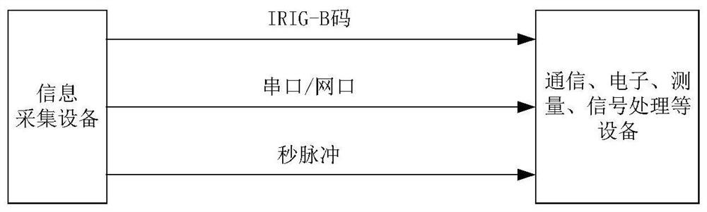
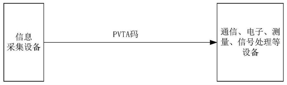
[0027] For the transmission of position, speed, time and attitude information using the traditional information transmission method, many types of data interfaces are required, and there are many corresponding drivers, which will result in many system communication lines, poor reliability, and large workload of interface debugging. The interface circuit is not easy to integrate and other problems. The present invention performs unified DC coding on the position, speed, time and attitude (PVTA) information, and organically combines the position, speed, time and attitude information to realize the simultaneous transmission of the position, speed, time and attitude information, such as figure 2 shown.
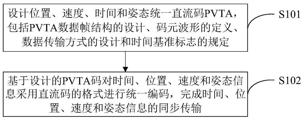
[0028] like image 3 As shown, a unified DC encoding method for position, velocity, time and attitude information, including:
[0029] Step S101: Design a unified DC code PVTA for position, speed, time and attitude, including the design of the PVTA data frame structure, the definition of the symbol waveform, the design of the data transmission mode, and the regulation of the time reference mark;
[0030] Step S102: The time, position, speed and attitude information are uniformly encoded in the DC code format based on the designed PVTA code to complete the synchronous transmission of the time, position, speed and attitude information.
[0031] Specifically, step S101 includes:
[0032] 1. Design of PVTA data frame structure
[0033] The structure of the PVTA data frame intuitively reflects the encoding format of the information data. It is stipulated that the frame period of the PVTA data frame is 1 second, each frame contains 1000 symbols, and each symbol corresponds to one data bit. Define the 0th symbol in the PVTA data frame as the reference symbol, namely P R; Define the 1-99th symbol as the data bit of the time information; define the 100-259th symbol as the data bit of the position information; define the 260-319th symbol as the data bit of the speed information; The 320th to 559th symbols are defined as the data bits of attitude information; the 560th to 999th symbols are defined as reserved data bits. The specific structure of PVTA data frame is as follows Figure 4 shown.
[0034] 2. Definition of symbol waveform
[0035] The PVTA data code includes three symbols P, 1, and 0 in total, and the symbol period is set to 1ms; the symbol P includes P R and P n , n = 0, 1, 2, 3, ... 99, P R is the reference symbol, P n For the position identification mark, the high-level width of symbol P is set to 800μs, and the low-level width is set to 200μs; the high-level width of symbol logic 1 is set to 500μs, and the low-level width is set to 500μs; symbol logic 0 is high-level The flat width is set to 200 μs, and the low level width is set to 800 μs. The waveform diagram of PVTA code symbol is as follows Figure 5 shown.
[0036] 3. PVTA symbol definition and data transmission method
[0037] The position, velocity, time and attitude information are uniformly encoded according to the above PVTA data frame structure, and the detailed symbol definitions are shown in Table 1. In the present invention, the length of time occupied by each bit of data encoded by the PVTA is fixed, and the serial transmission mode is adopted to transmit the data bit by bit in turn.
[0038] Table 1 PVTA code symbol definition table
[0039]
[0040]
[0041]
[0042]
[0043]
[0044]
[0045]
[0046]
[0047]
[0048]
[0049]
[0050] 4. Provisions of time reference marks
[0051] The time reference mark in the present invention is defined by the position identification mark P 0 and the adjacent reference symbol P R composition, both high-level widths are 800μs, and low-level widths are both 200μs, such as Image 6 shown; so if two symbols P are detected consecutively, the second symbol is the reference symbol P R , the leading edge and the rising edge of the second pulse are at the same time, that is, the time reference mark. Communication, electronics, measurement and signal processing equipment can achieve accurate time synchronization with this time base.
[0052] In order to make the present invention clearer, the present invention will be further described in detail below with reference to specific examples.
[0053] Assume that the position, speed, and attitude are sent at 10:45:17 a.m. on June 28, 2020, respectively 112.7° east longitude, 34.27° north latitude, 10 meters per second, azimuth angle 35°, pitch angle 30°, roll angle -20° information. After converting the above information into binary, they are:
[0054] (1) Time:
[0055] 1110 100 1010 001 0000 10 0000 0001 10 0000 0100
[0056] (2) Location:
[0057] longitude
[0058] 0000 0000 0000 0000 0000 0000 0000 0000 0000 1110 0110 0010 0100 10001000 0
[0059] latitude
[0060] 0000 0000 0000 0000 0000 0000 0000 0000 0111 0100 0110 0010 0010 11000000 0
[0061] (3) Speed:
[0062] 0000 0000 0000 0000 0000 0000 0110 0010 0000 1000 0000 0000
[0063] (4) Attitude:
[0064] direction angle
[0065] 0000 0000 0000 0000 0000 0000 0000 0000 0000 0000 0110 0010 1010 11000000
[0066] Pitch angle
[0067] 0000 0000 0000 0000 0000 0000 0000 0000 0000 0000 0110 0010 0000 11000000 0
[0068] roll angle
[0069] 0000 0000 0000 0000 0000 0000 0000 0000 0000 0000 0110 0010 0000 01000000 1
[0070] Combine the binary codes of time, position, velocity and attitude information according to the data format of Table 1 to form the corresponding PVTA code:
[0071] P R 1110 0 100P 1 1010 0 001 0P 2 0000 0 10 00P 3 0000 0 0001P 4 100000000P 5 0000 0 0100P 6 00000 0000P 7 0 0000 0 000P 8 000000000P 9 00000000 0P 10 0000 0 0000P 11 0000 0 0000P 12 0000 0 0000P 13 0000 0 0000P 14 0000 0 1110P 15 01100 0010P 16 0100 0 1000P 17 1000 0 0 000 P 18 0000 0 0000P 19 0000 0 0000P 20 0000 00000P 21 0000 0 0000P 22 0111 0 0100P 23 0110 0 0010P 24 0010 0 1100P 25 0000 0 0000P 26 0000 0 0000P 27 0000 0 0000P 28 0000 0 0000P 29 0110 0 0010P 30 0000 0 1000P 31 0000 0 0000P 32 0000 0 0000P 33 0000 0 0000P 34 0000 0 0000P 35 0000 0 0000P 36 00000 0000P 37 0110 0 0010P 38 1010 0 1100P 39 0000 0 0000P 40 0000 0 0000 P 41 0000 00000P 42 0000 0 0000P 43 0000 0 0000P 44 0000 0 0000P 45 0110 0 0010P 46 0000 01100P 47 0000 0 0 000P 48 0000 0 0000P 49 0000 0 0000P 50 0000 0 0000P 51 0000 00000P 52 0000 0 0000P 53 0110 0 0010P 54 0000 0 0100P 55 0000 0 1 000P 56 0000 00000P 57 0000 0 0000P 58 0000 0 0000P 59 0000 0 0000P 60 0000 0 0000P 61 0000 00000P 62 0000 0 0000P 63 0000 0 0000 P 64 0000 0 0000P 65 0000 0 0000P 66 0000 00000P 67 0000 0 0000P 68 0000 0 0000P 69 0000 0 0000P 70 0000 0 0000P 71 0000 00000P 72 0000 0 0000P 73 0000 0 0000P 74 0000 0 0000P 75 0000 0 0000P 76 0000 00000P 77 0000 0 0000P 78 0000 0 0000P 79 0000 0 0000P 80 0000 0 0000P 81 0000 00000P 82 0000 0 0000P 83 0000 0 0000P 84 0000 0 0000P 85 0000 0 0000P 86 0000 0 0000P 87 0000 0 0000P 88 0000 0 0000P 89 0000 0 0000P 90 0000 0 0000P 91 0000 0 0000P 92 0000 0 0000P 93 0000 0 0000P 94 0000 0 0000P 95 0000 0 0000P 96 0000 0 0000P 97 00000 0000P 98 0000 0 0000P 99 0000 0 0000P 0
[0072] Among them, P R -P 10 The data between is encoded for time information, P 10 -P26 The data between is encoded with position information, P 26 -P 32 The data between is encoded for speed information, P 32 -P 56 The data between is the attitude information encoding, P 56 -P 0 The data in between are reserved bits.
[0073] To sum up, the present invention performs unified DC coding on the position, speed, time, and attitude information, and realizes the organic combination and simultaneous transmission of the position, speed, time, and attitude information; the present invention performs unified DC coding on the position, speed, time, and attitude information. Coding simplifies the type of data interface, unifies the standard of the driver, reduces the workload of interface debugging, and improves the reliability of the information transmission system; the present invention can provide an external system with a Second pulse signal to achieve clock synchronization between external systems.
[0074] The above are only the preferred embodiments of the present invention. It should be pointed out that for those skilled in the art, without departing from the principles of the present invention, several improvements and modifications can be made. It should be regarded as the protection scope of the present invention.

PUM

no PUM

Description & Claims & Application Information

We can also present the details of the Description, Claims and Application information to help users get a comprehensive understanding of the technical details of the patent, such as background art, summary of invention, brief description of drawings, description of embodiments, and other original content. On the other hand, users can also determine the specific scope of protection of the technology through the list of claims; as well as understand the changes in the life cycle of the technology with the presentation of the patent timeline. Login to view more.

Similar technology patents

Vehicle body CAN bus controlling system

Owner:浙江中科正方电子技术有限公司

Flex-based monitoring page display method and system

ActiveCN102236709Areduce workloadeasy to generate
Owner:SHENZHEN ZTE NETVIEW TECH +1

Automatic report generating method capable of meeting power distribution network management specific data standards

InactiveCN103714492Areduce workloadVersatile and practical
Owner:GUANGXI POWER GRID ELECTRIC POWER RES INST +1

Classification and recommendation of technical efficacy words

  • reduce workload

Hospital gown

InactiveUS7181773B1reduce workloadquickly expose
Owner:WILLIAM BEAUMONT HOSPITAL

Performance Aware Peer-to-Peer Content-on-Demand

ActiveUS20090177792A1reduce workloadimproves perceive performance
Owner:THOMSON LICENSING SA

Garbage classification prompt garbage can and system based on image recognition

InactiveCN107054936Areduce workloadachieve reuse
Owner:GUANGDONG MATVIEW INTELLIGENT SCI & TECH CO LTD

Construction site operation safety remote management and control system and method

InactiveCN107967562AReduce workloadSave human and material resources
Owner:TAIYUAN POWER SUPPLY COMPANY OF STATE GRID SHANXI ELECTRIC POWER +1

Intelligent response method and system based on context dialogue semantic recognition

InactiveCN106357942AImprove recommendation hit ratereduce workload
Owner:GUANGZHOU BAILING DATA CO LTD
Why Eureka
Try Eureka