Eureka AIR delivers breakthrough ideas for toughest innovation challenges, trusted by R&D personnel around the world.

Locomotive auxiliary system power supply circuit and power supply control method

An auxiliary system and power supply circuit technology, which is applied in power lines, circuit devices, AC network circuits, etc., can solve the problems of frequent starting and stopping of auxiliary systems in non-electric areas, impact of contactor life, and high requirements for signal judgment accuracy in non-electric areas. Achieve the effect of ensuring continuous power and continuous work, saving power, and avoiding high requirements for judgment accuracy

Active Publication Date: 2020-12-25
ZHUZHOU ELECTRIC LOCOMOTIVE CO
View PDF18 Cites 2 Cited by
  • Summary
  • Abstract
  • Description
  • Claims
  • Application Information

AI Technical Summary

Problems solved by technology

[0005] The purpose of the present invention is to provide a power supply circuit and power supply control method for the auxiliary system of a locomotive to solve the problem of frequent start-up and stop of the auxiliary system in the non-electric zone, and to reconfigure the power supply circuit according to the signal in the non-electric zone to determine the precision requirements for the signal in the non-electric zone High, have a certain impact on the life of the contactor and other issues

Method used


Image

  • Locomotive auxiliary system power supply circuit and power supply control method
  • Locomotive auxiliary system power supply circuit and power supply control method
  • Locomotive auxiliary system power supply circuit and power supply control method

Examples


Embodiment Construction

[0061] The technical solutions in the present invention will be clearly and completely described below with reference to the accompanying drawings in the embodiments of the present invention. Obviously, the described embodiments are only a part of the embodiments of the present invention, not all of the embodiments. Based on the embodiments of the present invention, all other embodiments obtained by those of ordinary skill in the art without creative work fall within the protection scope of the present invention.

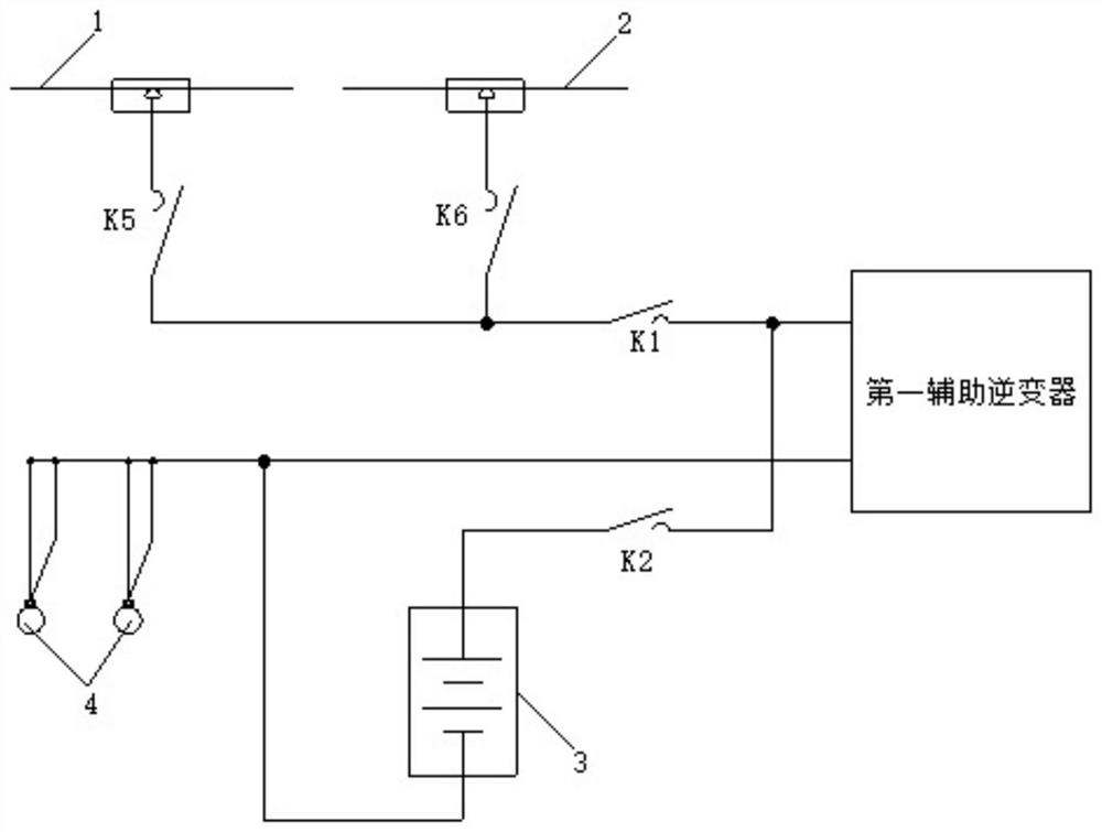
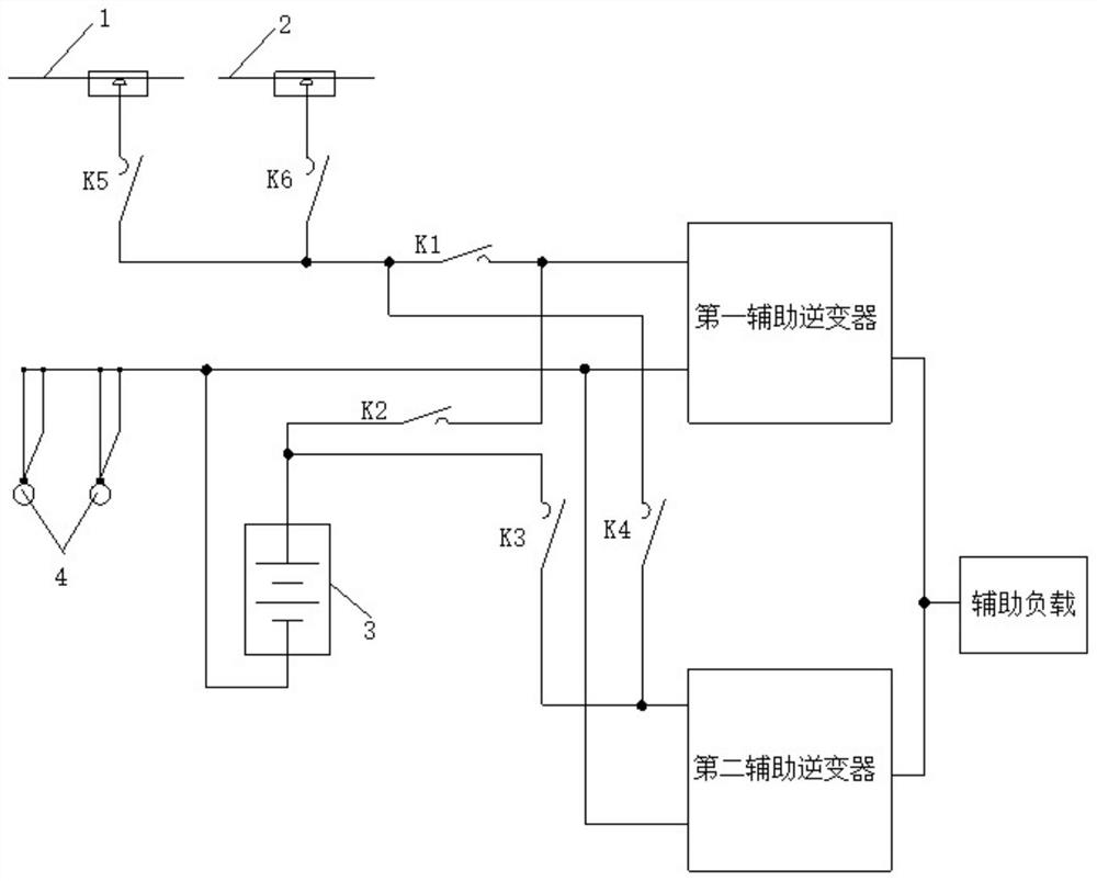
[0062] like figure 2 As shown, a power supply circuit for a locomotive auxiliary system provided in this embodiment includes a first auxiliary inverter, an energy storage power supply 3, a first contactor K1, a second contactor K2, a third rail 1 and an catenary 2 ; The first end of the first contactor K1 is respectively connected to the third rail 1 and the catenary 2, and the second end of the first contactor K1 is connected to the input end of the first auxiliar...


PUM


Abstract

The invention discloses a locomotive auxiliary system power supply circuit and power supply control method. An input side loop is controlled to work in different working modes according to working states of auxiliary inverters and power supply modes, and interlocking control of the working modes, the power supply modes, and the working states of the auxiliary inverters is performed. A first auxiliary inverter and a second auxiliary inverter are simultaneously started only in non-electrified zones, and an energy storage power source is not started in electrified zones, so that the electric quantity of the energy storage power source is saved. The sole working mode of the input side loop is determined according to the working states of the auxiliary inverters and the power supply modes before a locomotive enters the non-electrified zones so as to eliminate the need for frequent switching of contactors, reduce the influence on the service lives of the contactors, achieve automatic power supply switching between the electrified zones and the non-electrified zones, ensure continuous working of important auxiliary loads without power interruption, and avoid the problem of failure or lockout caused by frequent starting and stopping of the important auxiliary loads.

Description

technical field [0001] The invention belongs to the technical field of locomotive power supply control, and in particular relates to a power supply circuit and a power supply control method of a locomotive auxiliary system. Background technique [0002] When the locomotive is in operation, it obtains electric energy from the catenary or the third rail through the pantograph to drive the traction motor. For the third rail receiving urban rail subway line, in order to facilitate the passage of vehicles, the third rail must be interrupted at the fork section to form a dead zone. Taking the third rail power supply line of a certain subway as an example, the shortest dead zone is only 10 meters, and there are as many as 65 non-electric zones along the entire 20-kilometer line. [0003] Due to the different lengths and large number of design features of the dead zone of the subway line, when the vehicle passes through the dead zone, the auxiliary system will frequently start and ...

Claims


Application Information

Patent Timeline
Patent Type & Authority Applications(China)
IPC IPC(8): B60M3/00H02J3/00H02J9/06
CPCB60M3/00H02J3/0073H02J9/062
Inventor 王位郭婉露黄轩韬付茂林
Owner ZHUZHOU ELECTRIC LOCOMOTIVE CO
Why Eureka
Eureka Blog
Learn More