
Tunnel portal structure of shield interval

A technology for shield tunneling area and tunnel door, applied in the field of tunnel door structure, can solve problems such as the difficulty in implementing flood-proof doors, and achieve the effect of preventing submerged tunnels and avoiding water and sand gushing.

Pending Publication Date: 2020-12-25
FOSHAN RAIL TRANSIT DESIGN & RES INST CO LTD
View PDF1 Cites 0 Cited by
  • Summary
  • Abstract
  • Description
  • Claims
  • Application Information

AI Technical Summary

Problems solved by technology

However, when the portal needs to be equipped with an anti-flooding door, after the external hanging door structure is installed at the entrance, the external ring beam at the entrance conflicts with the anti-flooding door, which makes it difficult to implement the anti-flooding door

Method used


Image

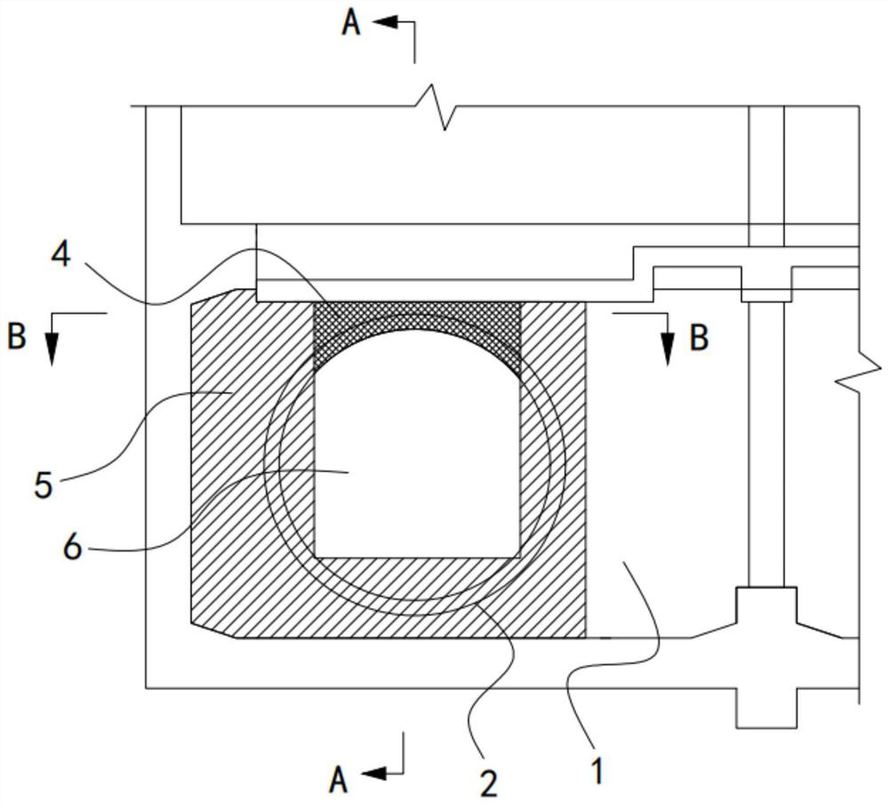
  • Tunnel portal structure of shield interval
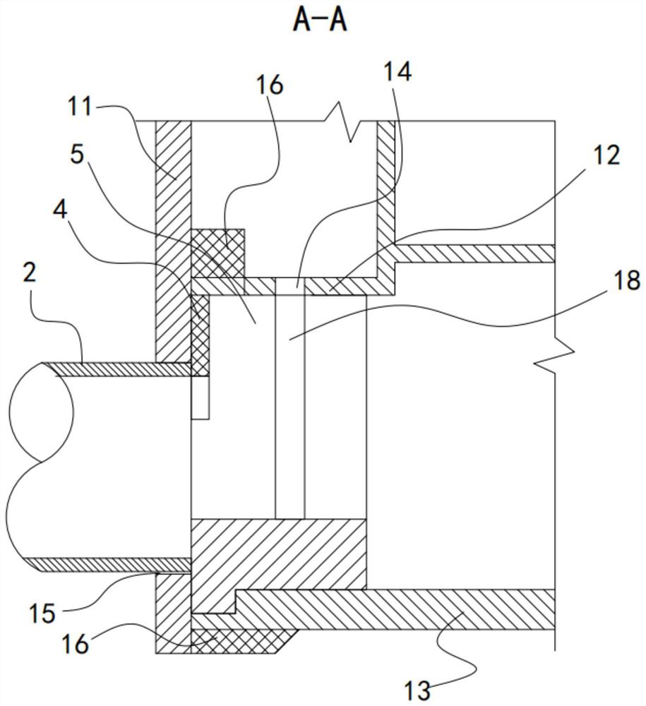
  • Tunnel portal structure of shield interval
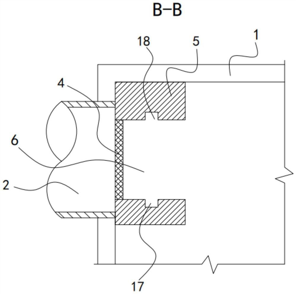
  • Tunnel portal structure of shield interval

Examples


Embodiment Construction

[0032] The specific implementation manners of the present invention will be further described in detail below in conjunction with the accompanying drawings and embodiments. The following examples are used to illustrate the present invention, but are not intended to limit the scope of the present invention.

[0033] In describing the present invention, it should be understood that the terms "center", "longitudinal", "transverse", "length", "width", "thickness", "upper", "lower", "front", " Orientation or position indicated by "back", "left", "right", "vertical", "horizontal", "top", "bottom", "inner", "outer", "clockwise", "counterclockwise", etc. The relationship is based on the orientation or positional relationship shown in the drawings, and is only for the convenience of describing the present invention and simplifying the description, rather than indicating or implying that the referred device or element must have a specific orientation, be constructed and operated in a sp...


PUM


Abstract

The invention relates to the technical field of subway civil construction, and discloses a tunnel portal structure of a shield interval. The tunnel portal structure comprises a wall body, a door frame, an arch wall and a flood gate, wherein the wall body is provided with a hole channel used for communicating with the shield interval; a door hole is formed in the top wall of the hole channel; the door frame is arranged in the hole channel; a U-shaped groove which is provided with an upward opening and communicates with the door hole is formed in the door frame; the outer wall of the door frameis attached to the inner wall of the hole channel; sliding grooves are formed in the two side walls of the U-shaped groove and extend in the vertical direction; one end of the arch wall is attached tothe wall body; the flood gate is arranged in the door hole in a penetrating mode and extends into the U-shaped groove; and one side of the flood gate is slidably arranged in the first sliding groove,and the other side of the flood gate is slidably arranged in the second sliding groove. The flood gate is slidably connected to the door frame, when a large amount of flood flows in, the flood gate can seal the hole channel, the blocking effect is formed, and the flood is prevented from submerging the hole channel.

Description

technical field [0001] The invention relates to the technical field of subway civil construction, in particular to a portal structure in a shield section. Background technique [0002] With the large-scale construction of urban subways, the construction of the portal at the interface between the shield section tunnel and the main structure of the station has always been a risk point. It will affect the water stop at the interface, and if it is not handled properly, it will easily cause water and sand gushing accidents. [0003] In order to prevent water and sand inrush accidents, in the traditional portal structure, an embedded portal structure is adopted. After removing the shield segment at the interface between the tunnel and the station, the portal ring beam is poured so that the outer end surface of the portal ring beam is in contact with the station. The inner wall of the end wall is flush. In this way, the depth of the shield segment that needs to be chiseled out is...

Claims


Application Information

Patent Timeline
Patent Type & Authority Applications(China)
IPC IPC(8): E21F17/103E21F17/12E21D9/14E21D11/38E02D29/045
CPCE21F17/103E21F17/12E21D9/14E21D11/38E02D29/04
Inventor 陈相宇张勇冯建霖潘茜周灿朗林湘刘加福邓嘉宁
Owner FOSHAN RAIL TRANSIT DESIGN & RES INST CO LTD
Learn More