Flexible power generation device and power generation backpack applying same

A power generation device and flexible technology, applied in applications, household appliances, machines/engines, etc., can solve problems such as insufficient power of electrical appliances, and achieve the effect of diverse application occasions and strong practicability

Pending Publication Date: 2020-12-25
NANJING UNIV OF POSTS & TELECOMM +1
View PDF0 Cites 7 Cited by
  • Summary
  • Abstract
  • Description
  • Claims
  • Application Information

AI Technical Summary

Problems solved by technology

When doing outdoor activities, it is inevitable to encounter the situation of insufficient electrical power, which brings a lot of inconvenience

Method used


Image

  • Flexible power generation device and power generation backpack applying same
  • Flexible power generation device and power generation backpack applying same
  • Flexible power generation device and power generation backpack applying same

Examples


Embodiment 1

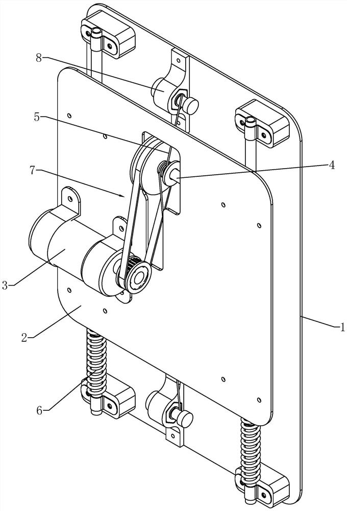
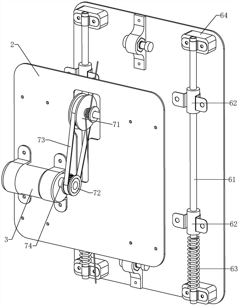
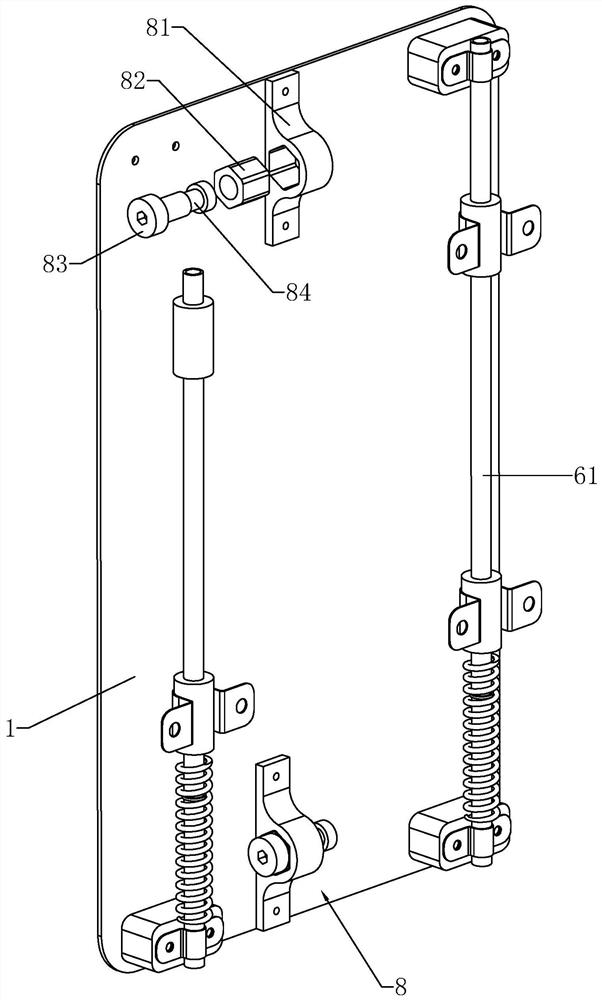
[0031] Example 1: Reference Figure 1-4 , a flexible power generation device, including a backboard 1 and a slider 2 that can slide relatively, a rebound mechanism 6 for driving the backplane 1 to slide upward is provided between the backboard 1 and the slider 2, and a generator 3 is fixed on the slider 2 , the sliding plate 2 is rotatably connected with a rotating shaft 4, which is arranged horizontally, and the rotating shaft 4 and the generator 3 rotate in the same direction through the one-way transmission mechanism 7, and the rotating shaft 4 is wound with a rope 5, and the upper and lower ends of the backboard 1 are fixed. There is a rope tightener 8, and the upper and lower ends of the rope 5 are fixed on the rope tightener 8, and the rope tightener 8 is used to make the rope 5 in a taut state.

[0032] refer to Figure 1-4 , the present invention is mainly used in the field of backpacks. The backboard 1 is fixed. When a person is walking or running, the center of grav...

Embodiment 2

[0037] Example 2: Reference Figure 1-6 , a power generation backpack, including a strap 92 assembly, a bag body 91 and the power generation device in Embodiment 1. The back plate 1 of the power generation device is fixedly connected with the strap 92 assembly, and the bag body 91 is vertically provided with a bar-shaped hole, and the driving wheel 71 slides in the bar-shaped groove; the slide plate 2 is located inside the bag body 91 and is fixedly connected with the bag body 91 . When people are carrying a backpack, their center of gravity will change when they are walking outdoors. Under the action of inertia, the skateboard 2 and the backboard 1 will slide relative to each other, and the mechanical energy of this part will be converted into electrical energy. During the relative sliding process of the slide plate 2 and the back plate 1, the rope 5 drives the rotating shaft 4 to rotate, and further drives the generator 3 to rotate through the one-way transmission mechanism...


PUM


Abstract

The invention relates to a flexible power generation device and a power generation backpack applying the same. The flexible power generation device comprises a back plate and a sliding plate capable of sliding relatively. A resilient mechanism for driving the sliding plate to slide upward is arranged between the back plate and the sliding plate. A generator is fixed to the sliding plate. A rotating shaft is rotatably connected to the sliding plate. The rotating shaft and the generator rotate homodromously through a single-direction transmission mechanism. A rope winds the rotating shaft, ropefasteners are fixed to the upper and lower ends of the back plate. The upper and lower ends of the rope are fixed to the rope fasteners. When the sliding plate slides downward, the rotating shaft is pulled by the rope to rotate, the rotating shaft drives the generator to rotate in a single direction to generate electricity through the single-direction transmission mechanism, and the resilient mechanism is compressed to have an elastic force so as to drive the sliding plate to reset. The power generation device is not affected by an environment, and the resilient mechanism can collect mechanical energy generated by the backpack which vibrates up and down when a human body walks or runs, and the mechanical energy is further converted into electric energy.

Description

technical field [0001] The invention relates to the technical field of wearable power generation equipment, and more specifically, it relates to a flexible power generation device and a power generation backpack using the device. Background technique [0002] Currently, with the vigorous development of wearable electronic device technology, people's demand for wearable electronic devices is getting higher and higher. It is unavoidable to encounter the situation of insufficient electric power of electrical appliances during outdoor activities, which brings a lot of inconvenience. Wearable power generation devices can meet the power supply needs of electronic devices through the energy generated by the human body's own activities. [0003] Mechanical energy is the main energy source supporting the daily activities of the human body, and it has a high energy density. However, only a small percentage of the mechanical energy produced by the human body is used to support human ...

Claims


Application Information

Patent Timeline
Patent Type & Authority Applications(China)
IPC IPC(8): F03G7/08A45F3/08
CPCA45F3/08F03G7/08
Inventor 曹自平刘立晨孙洪波
Owner NANJING UNIV OF POSTS & TELECOMM
Why Eureka
Try Eureka