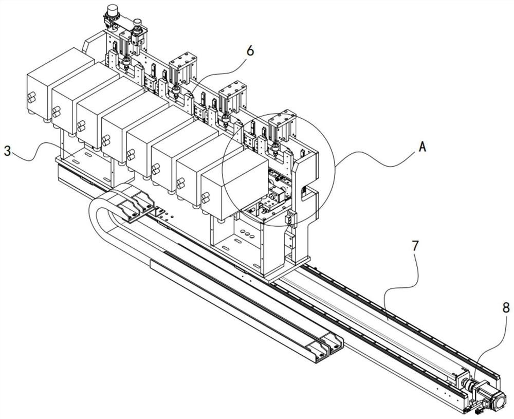
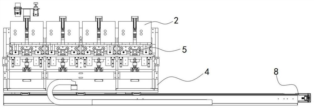
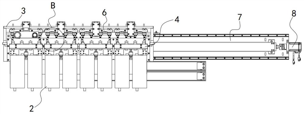
Leakage detection device on blood path tube production line

A production line and leak detection technology, applied in the field of blood vessels, can solve the problems of difficult to eliminate errors, difficult to define the pressure drop threshold, inaccurate measurement, etc., to eliminate the influence, improve the accuracy of leak detection, and the effect of accurate leak detection.

Pending Publication Date: 2020-12-25
贝恩医疗设备(广州)有限公司
View PDF0 Cites 0 Cited by
  • Summary
  • Abstract
  • Description
  • Claims
  • Application Information

AI Technical Summary

Problems solved by technology

[0005] However, there is a leak detection error of about 10% in the existing method, that is, 10% of the blood tubes that are judged to be unqualified are actually qualified products
This is because the blood line tube is made of soft material, and its actual volume is expanded by inflation when it is inflated, resulting in a decrease in the gas pressure in the blood line tube and an additional pressure drop, resulting in inaccurate measurement
[0006] In the prior art, when a constant pressure drop threshold is used to test blood tubes produced at different temperatures, errors will inevitably occur due to differences in the expansion coefficients of the blood tubes
At the same time, because the expansion coefficient of the blood tube is greatly affected by the ambient temperature, it is difficult to define the pressure drop threshold at each temperature, which makes it difficult to eliminate this error

Method used


Image

  • Leakage detection device on blood path tube production line
  • Leakage detection device on blood path tube production line
  • Leakage detection device on blood path tube production line

Examples


Embodiment Construction

[0028] The specific implementation manners of the present invention will be further described in detail below in conjunction with the accompanying drawings and embodiments. The following examples are used to illustrate the present invention, but are not intended to limit the scope of the present invention.

[0029] In describing the present invention, it is to be understood that the terms "center", "longitudinal", "transverse", "length", "width", "thickness", "upper", "lower", "front", " Orientation or position indicated by "back", "left", "right", "vertical", "horizontal", "top", "bottom", "inner", "outer", "clockwise", "counterclockwise", etc. The relationship is based on the orientation or positional relationship shown in the drawings, and is only for the convenience of describing the present invention and simplifying the description, rather than indicating or implying that the referred device or element must have a specific orientation, be constructed and operated in a spe...


PUM


Abstract

The invention relates to the technical field of blood path tubes, and discloses a leakage detection device on a blood path tube production line. The leakage detection device comprises a first sensor,a second sensor, an air supply mechanism, a first platform, a second platform and a first driving mechanism, wherein the first sensor is used for collecting a first air pressure value in a first bloodpath tube, the second sensor is used for collecting a second air pressure value in a second blood path tube, the air supply mechanism is used for supplying air to the first blood path tube and the second blood path tube, the first platform is provided with a first sliding rail, the second platform is arranged on the first sliding rail in a sliding mode, and the first driving mechanism is used fordriving the second platform to be switched between an air supply position and a disconnection position in a sliding mode; and when the second platform is driven to the air supply position by the first driving mechanism, the air supply mechanism is connected with the first blood path tube through a first sleeve, and the air supply mechanism is connected with the second blood path tube through a second sleeve. According to the leakage detection device, the air pressure reduction amount of the two blood path tubes can be detected at the same time, the influence of the temperature on the leakagedetection result can be effectively eliminated, and the leakage detection accuracy of the blood path tubes is improved.

Description

technical field [0001] The invention relates to the technical field of blood tubes, in particular to a leak detection device on a blood tube production line. Background technique [0002] A blood line tube, also known as a hemodialysis line, is used for hemodialysis treatment, and generally includes a line and joints on both sides of the line. [0003] When producing on the production line, it is necessary to set up a leak detection station for leak detection of the blood line tubes to ensure that the air tightness of the produced blood line tubes meets the requirements. In the leak detection station, multiple blood tubes are regularly arranged on the conveyor belt, and the conveyor belt moves along the flow direction of the production line. [0004] In the prior art, when testing the airtightness of leaking blood tubes, the blood tubes to be tested are generally tested individually one by one. The specific method is: fill the blood tubes to be tested with gas and seal them...

Claims


Application Information

Patent Timeline
Patent Type & Authority Applications(China)
IPC IPC(8): G01M3/28G01M3/08B65G47/90
CPCB65G47/901G01M3/08G01M3/2815
Inventor 廖磊
Owner 贝恩医疗设备(广州)有限公司
Why Eureka
Try Eureka