Check patentability & draft patents in minutes with Patsnap Eureka AI!

Switch loop detection method and device

A technology of loop detection and switches, applied in the field of switches, can solve the problems of occupying port bandwidth, large bandwidth and CPU resources, etc., and achieve the effect of reducing the burden of CPU, reducing network bandwidth overhead, and avoiding traffic storms

Active Publication Date: 2020-12-25
SUZHOU LANGCHAO INTELLIGENT TECH CO LTD
View PDF5 Cites 3 Cited by
  • Summary
  • Abstract
  • Description
  • Claims
  • Application Information

AI Technical Summary

Benefits of technology

This technology helps prevent overcrowding networks caused by looping between devices that are connected together without being detected properly or causing delays during communication. It sends an announcement request for new connections along with its own identifier (ID) into the system's interface. A router then checks if any two IDs match up before sending their requested packets back downstream towards another computer called Baseboard Management Control System (BMC). If they don’t meet certain criteria, it will transfer some files onto other computers until there were enough space left around each machine.

Problems solved by technology

This patented technical problem addressed in this patents relates to reducing wasted communication over wireless networks caused by excessive data transmission during certain periods while maintaining high efficiency in transmitting signals between devices connected wirelessly without increasing interference levels that could cause signal delays due to increased power usage.

Method used


Image

  • Switch loop detection method and device
  • Switch loop detection method and device
  • Switch loop detection method and device

Examples


Embodiment Construction

[0040] In order to make the object, technical solution and advantages of the present invention clearer, the embodiments of the present invention will be further described in detail below in conjunction with specific embodiments and with reference to the accompanying drawings.

[0041] It should be noted that all expressions using "first" and "second" in the embodiments of the present invention are to distinguish two entities with the same name but different parameters or parameters that are not the same, see "first" and "second" It is only for the convenience of expression, and should not be construed as a limitation on the embodiments of the present invention, which will not be described one by one in the subsequent embodiments.

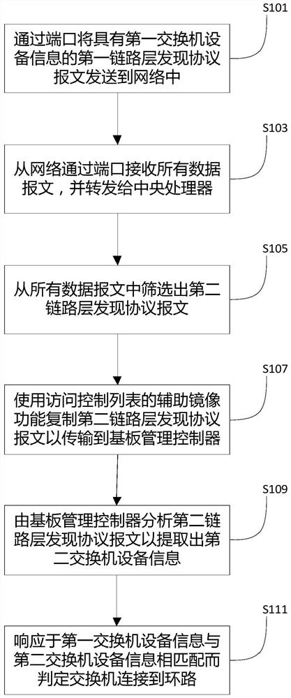
[0042] Based on the above purpose, the first aspect of the embodiments of the present invention proposes an embodiment of a switch loop detection method that reduces network bandwidth overhead during loop detection, avoids traffic storms, and reduces...


PUM


Abstract

The invention discloses a switch loop detection method and device. The method comprises the steps: sending, by a port, a first link layer discovery protocol message with first switch equipment information to a network; receiving all data messages from the network through the port and forwarding the data messages to the central processing unit; screening out a second link layer discovery protocol message from all the data messages; copying the second link layer discovery protocol message by using an auxiliary mirroring function of the access control list so as to transmit the second link layerdiscovery protocol message to the baseboard management controller; analyzing, bythe baseboard management controller, the second link layer discovery protocol message to extract second switch equipmentinformation; and determining the switch to be connected to the loop in response to the first switch device information matching the second switch device information. According to the invention, the network bandwidth overhead can be reduced when the loop is detected, the traffic storm is avoided, and the burden of the CPU is reduced.

Description


Claims


Application Information

Patent Timeline
Owner SUZHOU LANGCHAO INTELLIGENT TECH CO LTD
Features
  • R&D
  • Intellectual Property
  • Life Sciences
  • Materials
  • Tech Scout
  • Unparalleled Data Quality
  • Higher Quality Content
  • 60% Fewer Hallucinations
Learn More