Large-section reinforcing steel bar upsetting machine with high upsetting speed for reinforced concrete machining

A reinforced concrete, high-speed technology, applied in the field of large-section steel bar upsetting machine, can solve the problems of troublesome installation and disassembly, increase labor intensity, reduce production efficiency, etc., and achieve the effect of convenient removal operation

Inactive Publication Date: 2020-12-29
李慧迪
View PDF6 Cites 0 Cited by
  • Summary
  • Abstract
  • Description
  • Claims
  • Application Information

AI Technical Summary

Problems solved by technology

[0002] In the process of engineering construction, when the steel bar head of reinforced concrete is threaded, in order to ensure that the steel bar meets the strong connection requirements at the joint, the steel bar head needs to be upset to ensure that the steel bar joint has a sufficient cross-sectional area, and then processed Thread, so that the actual cross-sectional area after processing is larger than the original steel bar cross-sectional area, greatly improving the tensile strength of the joint, making it suitable for projects with high connection strength requirements. In the prior art, the fixtures on the steel bar upsetting machine are mostly through multiple When fixing different types of steel bars, multiple bolts need to be disassembled and installed multiple times, which makes installation and disassembly more troublesome, increases people's labor intensity, and reduces production efficiency. Therefore, a large-section steel bar upsetting machine with fast upsetting speed for reinforced concrete processing is of great practical value.

Method used


Image

  • Large-section reinforcing steel bar upsetting machine with high upsetting speed for reinforced concrete machining
  • Large-section reinforcing steel bar upsetting machine with high upsetting speed for reinforced concrete machining
  • Large-section reinforcing steel bar upsetting machine with high upsetting speed for reinforced concrete machining

Examples


Embodiment Construction

[0021] The following will clearly and completely describe the technical solutions in the embodiments of the present invention with reference to the accompanying drawings in the embodiments of the present invention. Obviously, the described embodiments are only some, not all, embodiments of the present invention. Based on the embodiments of the present invention, all other embodiments obtained by persons of ordinary skill in the art without making creative efforts belong to the protection scope of the present invention.

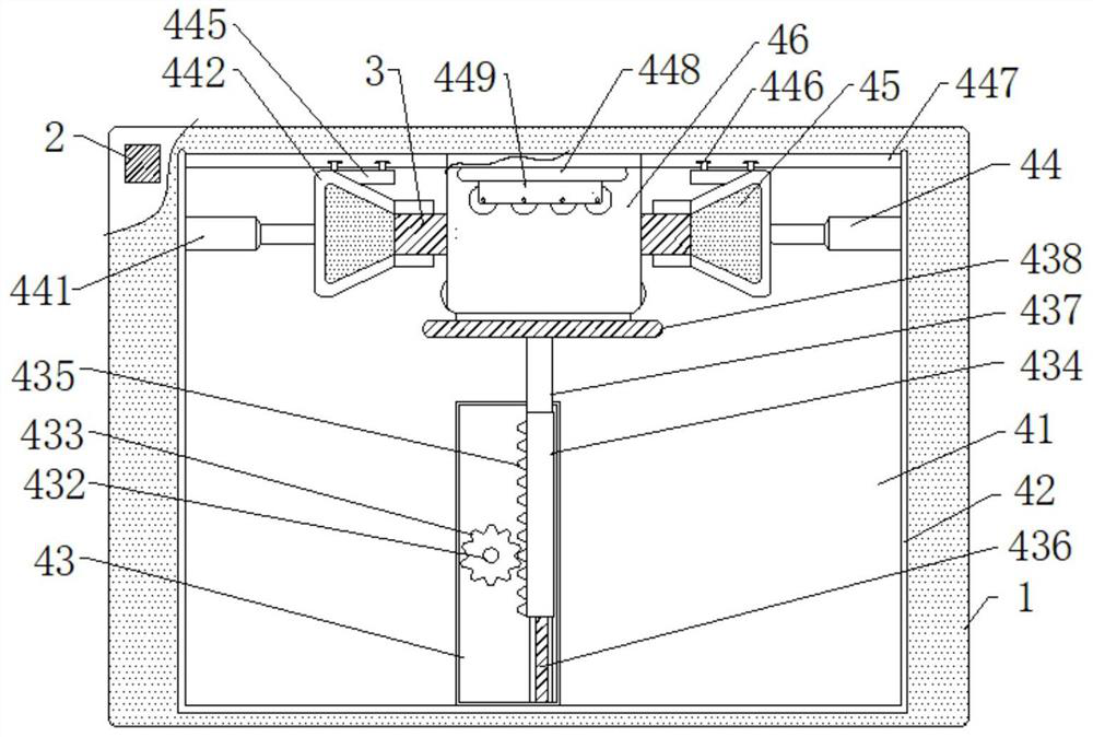
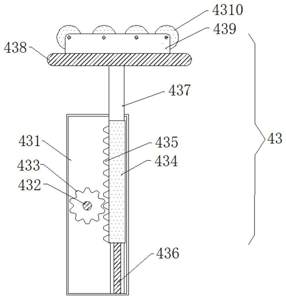
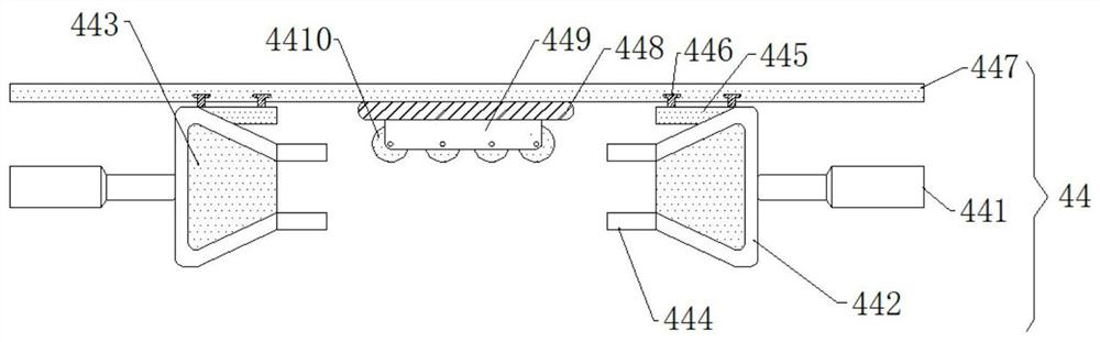
[0022] see figure 1 , the present invention provides a technical scheme of a large-section steel bar upsetting machine with fast upsetting speed for reinforced concrete processing, including a workbench 1, the bottom of the workbench 1 is evenly provided with outriggers 2, and the top of the workbench 1 is provided with an upsetting device 4 The upsetting device 4 includes a base plate 41, a C-shaped enclosure 42 is arranged on the top of the base plate 41, an...


PUM


Abstract

The invention discloses a large-section reinforcing steel bar upsetting machine with the high upsetting speed for reinforced concrete machining in the technical field of reinforcing steel bar machining machines. The large-section reinforcing steel bar upsetting machine comprises a workbench, supporting legs are evenly arranged at the bottom of the workbench, an upsetting device is arranged at thetop of the workbench, the upsetting device comprises a base plate, a C-shaped surrounding plate is arranged at the top of the base plate, an upsetting assembly is arranged on the side wall of the C-shaped surrounding plate, an ejection piece and an upper anti-deformation piece are arranged on the upsetting assembly, the top of the C-shaped surrounding plate is connected with a side anti-deformation piece, the side anti-deformation piece comprises a connecting plate, the connecting plate is fixedly welded to the top of the base plate, a first main serrated wheel is arranged above the connectingplate, and a first motor shaft is inserted into an inner cavity of the first main serrated wheel. According to the reinforcing steel bar upsetting machine, different types of reinforcing steel bars can be conveniently subjected to upsetting operation, in addition, after the reinforcing steel bars are upset, the reinforcing steel bars can be conveniently taken down, and therefore, the upsetting efficiency of the reinforcing steel bars is improved.

Description

technical field [0001] The invention relates to the technical field of steel bar processing machinery, in particular to a large-section steel bar upsetting machine with high upsetting speed for reinforced concrete processing. Background technique [0002] In the process of engineering construction, when the steel bar head of reinforced concrete is threaded, in order to ensure that the steel bar meets the strong connection requirements at the joint, the steel bar head needs to be upset to ensure that the steel bar joint has a sufficient cross-sectional area, and then processed Thread, so that the actual cross-sectional area after processing is larger than the original steel bar cross-sectional area, greatly improving the tensile strength of the joint, making it suitable for projects with high connection strength requirements. When fixing different types of steel bars, multiple bolts need to be disassembled and installed multiple times, which makes installation and disassembly...

Claims


Application Information

Patent Timeline
IPC IPC(8): B21F5/00
CPCB21F5/005
Inventor 李慧迪
Owner 李慧迪
Why Eureka
Try Eureka