Optical fiber cable

A technology of optical fiber cables and optical fibers, applied in the field of optical fiber cables, to achieve the effects of reducing the number of uses, easy removal operations, and easy manufacturing

Active Publication Date: 2019-02-05
THE FUJIKURA CABLE WORKS LTD +1
View PDF27 Cites 3 Cited by
  • Summary
  • Abstract
  • Description
  • Claims
  • Application Information

AI Technical Summary

Problems solved by technology

[0008] However, in the case of taking out the optical fiber cable of Patent Document 2, it is necessary to use a secondary tool when cutting the outer sheath and the reinforcement sheet and when cutting the inner sheath.
In addition, a large force is required when tearing the reinforcement sheet and the outer sheath with the tear cord

Method used


Image

  • Optical fiber cable
  • Optical fiber cable
  • Optical fiber cable

Examples


no. 1 Embodiment approach

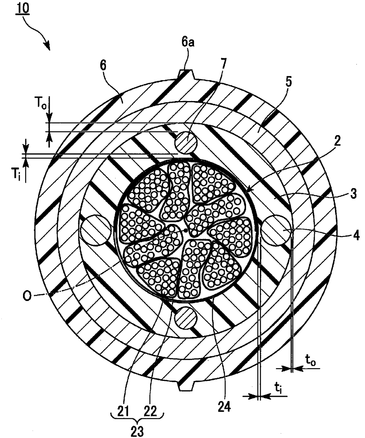
[0055] Below, refer to figure 1 , figure 2 , the structure of the optical fiber cable 10 of the first embodiment will be described. In addition, the scales of the drawings used in the following description are appropriately changed so that the shape of each component can be recognized.

[0056] like figure 1 As shown, the optical fiber cable 10 includes a core 2 , an inner sheath 3 , a pair of linear bodies 4 , a pair of tensile members 7 (tension members), a reinforcing sheet 5 , and an outer sheath 6 .

[0057] (direction definition)

[0058] Here, in this embodiment, the inner sheath 3 , the reinforcing sheet 5 , and the outer sheath 6 are formed in a cylindrical shape having a common central axis O.

[0059] In this embodiment, the direction along the central axis O is referred to as the longitudinal direction. In addition, a section perpendicular to the longitudinal direction is referred to as a transverse section, and a section along the longitudinal direction is r...

no. 2 Embodiment approach

[0112] Next, a second embodiment of the present invention will be described, but the basic configuration is the same as that of the first embodiment. Therefore, the same reference numerals are assigned to the same configurations, their descriptions are omitted, and only different points will be described.

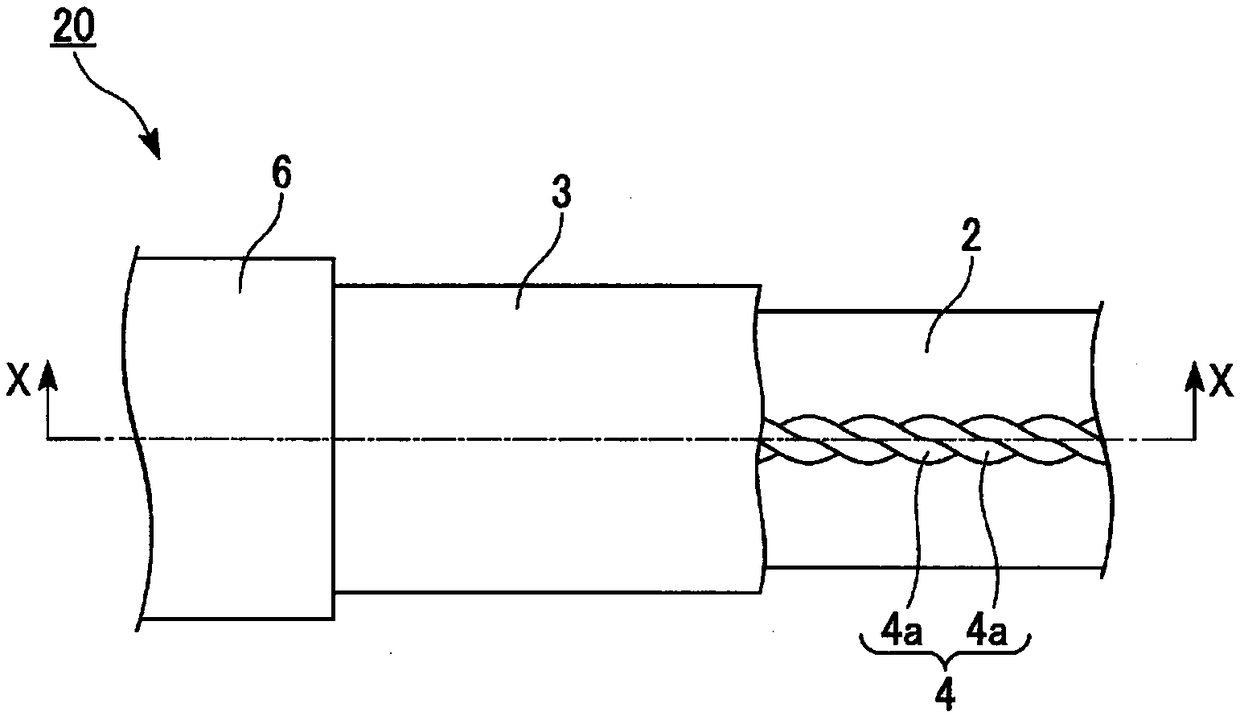
[0113] Such as Figure 3A , Figure 3B As shown, the optical fiber cable 20 of the second embodiment differs from the first embodiment in the form of the strip body 4 and the inner sheath 3 .

[0114] The thread body 4 of the second embodiment is formed of a yarn (yarn: yarn) twisted with fibers such as PP and polyester. exist Figure 3A , Figure 3B In the example shown, the linear body 4 is formed by further twisting a plurality of plain yarns 4a which are yarns. also, Figure 3A It is an explanatory diagram showing the structure of the optical fiber cable 20 according to the second embodiment, and the illustration of each structure is partially omitted. Specifical...

no. 3 Embodiment approach

[0125] Next, a third embodiment of the present invention will be described, but the basic configuration is the same as that of the first embodiment. Therefore, the same reference numerals are assigned to the same configurations, their descriptions are omitted, and only the differences will be described.

[0126] Figure 5 The optical fiber cable 30 of the third embodiment shown differs from the first embodiment in that the linear body 4 is fixed to the reinforcement sheet 5 .

[0127] Such as Figure 5 As shown, the line body 4 of the third embodiment is fixed to the reinforcing sheet 5 via the fixing portion 8 and the fixing layer 9 . The fixing portion 8 is formed of, for example, an adhesive. The fixing layer 9 is formed by attaching, for example, a PET sheet to the inner peripheral surface of the reinforcing sheet 5 with an adhesive. The fixing layer 9 is formed over the entirety of the inner peripheral surface of the reinforcing sheet 5 . Thereby, for example, even w...


PUM


Abstract

The optical fiber cable according to the present invention is provided with a core in which a plurality of optical fibers are gathered, an inside sheath for accommodating the core therein, a filamentbody embedded in the inside sheath, a pair of tension members embedded in the inside sheath with the core therebetween, a reinforcing sheet for covering the inside sheath and the filament body, and anoutside sheath for covering the reinforcing sheet, the expressions ti < Ti and to < To being satisfied, where ti is the thickness of a portion of the inside sheath on the inside in the radial direction of the filament body, Ti is the thickness of a portion of the inside sheath on the inside of the pair of tension members in the radial direction, to is the thickness of a portion of the inside sheath on the outside of the filament body in the radial direction, and To is the thickness of a portion of the inside sheath on the outside of the pair of tension members in the radial direction.

Description

technical field [0001] The present invention relates to fiber optic cables. [0002] This application claims the priority of Japanese Patent Application No. 2016-153695 filed in Japan on August 4, 2016, and uses the content here. Background technique [0003] Fiber optic cables that are erected, laid, or buried (hereinafter referred to as "installation") in mountains or forests may be bitten by wild animals such as mice, squirrels, and woodpeckers, and collide with flying objects such as hunting bullets. Case. In such a case, the optical fiber inside the optical fiber cable may be damaged. In order to prevent such damage, the optical fiber cable disclosed in Patent Document 1 is protected by covering the optical fiber with a reinforcing sheet. [0004] Here, in an optical fiber cable having a reinforcing sheet, when detaching or connecting an installed optical fiber, the work of cutting the reinforcing sheet or the like and taking out the optical fiber from the inside (he...

Claims


Application Information

Patent Timeline
Patent Type & Authority Applications(China)
IPC IPC(8): G02B6/44
CPCG02B6/441G02B6/4433G02B6/4486G02B6/566G02B6/4431G02B6/44G02B6/4416
Inventor 伊佐地瑞基大野正敏佐藤真之介富川浩二鲶江彰大里健中川直树青柳雄二铁谷成且
Owner THE FUJIKURA CABLE WORKS LTD
Why Eureka
Try Eureka