

Heavy equipment pusher jack
A technology of heavy equipment and pushing device, applied in the direction of hoisting device, hoisting device, etc., can solve the problems of low manual moving efficiency, difficult equipment, troublesome moving, etc., and achieve the effect of maintaining stability and reliability, and scientific design.
Inactive Publication Date: 2020-12-29
湖南臻镜绿色建筑科技有限公司
View PDF0 Cites 0 Cited by
- Summary
- Abstract
- Description
- Claims
- Application Information
AI Technical Summary
Problems solved by technology
[0002] In light wall panel production units, due to the need for production and processing, it is difficult to move heavy equipment because there are not many opportunities for equipment movement, so it is difficult to have special moving equipment. Usually, the factory will use forklifts or manual direct movement. For processing, using a forklift to move will inevitably affect the stable combination of equipment components, and it will also damage the equipment due to improper operation. Manual direct movement will cause unsafe phenomena due to cumbersomeness, and manual movement also has problems of low efficiency and troublesome movement.
Method used
View moreImage
Smart ImageViewing Examples

Examples
Embodiment Construction
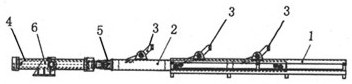
[0009] figure 1 Shown: The device used for sliding push of heavy equipment is equipped with a sliding sliding push rod shaft 2 installed in the guide base 1 with a sliding space inside, and several pushing connectors 3 are connected to the outside of the sliding push rod shaft 2 , the tail end of the sliding push rod shaft 2 is coaxially connected to push the oil cylinder 4 through the hinge seat 5 . Pushing the oil cylinder 4 is provided with an oil cylinder fixing seat 6 .
Login to View More PUM
 Abstract
The invention provides a heavy equipment pusher jack. The heavy equipment pusher jack is characterized in that a device for sliding and pushing heavy equipment is provided with a slidable sliding pushrod shaft in a guide base internally provided with a sliding space, the outer side of the sliding push rod shaft is connected to a plurality of pushing connectors, and the tail end of the sliding push rod shaft is coaxially connected to a pushing oil cylinder through a hinge seat. When the heavy equipment pusher jack is used, the pushing connectors can be connected to heavy equipment needing to be pushed, and after the pushing oil cylinder is started, the heavy equipment can be stably pushed to slide by the oil cylinder.
Description
technical field [0001] The invention relates to a device for moving heavy equipment, in particular to a heavy equipment moving device. Background technique [0002] In light wall panel production units, due to the need for production and processing, it is difficult to move heavy equipment because there are not many opportunities for equipment movement, so it is difficult to have special moving equipment. Usually, the factory will use forklifts or manual direct movement. For processing, using a forklift to move will inevitably affect the stable combination of equipment components, and will damage the equipment due to improper operation. Manual direct movement will cause unsafe phenomena due to cumbersomeness, and manual movement also has problems of low efficiency and troublesome movement. Contents of the invention [0003] The technical purpose of the present invention is to solve the above-mentioned existing problems, and provide a heavy equipment moving device, which can...
Claims
Login to View More Application Information
Patent Timeline
 IPC IPC(8): B66F19/00
CPCB66F19/00
Inventor危佳
Owner湖南臻镜绿色建筑科技有限公司