Check column valve
A column valve and single-flow technology, which is applied in the field of single-flow column valves, can solve the problems of large land occupation, high cost, time-consuming and labor-intensive operation of personnel, etc., and achieve the effect of reducing land occupation, reducing valves, and simple operation
- Summary
- Abstract
- Description
- Claims
- Application Information
AI Technical Summary
Problems solved by technology
Method used
Image

Examples
Embodiment 1
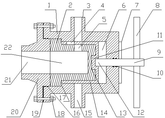
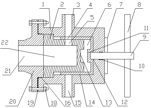
[0022] like figure 1 As shown, a single-flow column valve, the technical solution of the present invention is: a single-flow column valve, comprising: a valve body 1, a valve body chamber 6 is arranged in the valve body 1, and the valve body 1 is circumferentially arranged There are several valve body connecting pipes 3, the valve body connecting pipe 3 communicates with the valve body chamber 6 through the valve body connecting pipe flow channel 15; the valve core 2, the valve core 2 is provided with a valve core chamber 22, the valve core 2 The valve core 2 is provided with a sliding sleeve 14, the valve core 2 and the sliding sleeve 14 are rotatably installed in the valve body cavity 6, and the valve core 2 is provided with a valve core hole 5 in the circumferential direction. The sleeve 14 is provided with a sliding sleeve hole 4 in the circumferential direction; the end cover 20 is fixedly connected with the valve body 1, and the end cover 20 is provided with an end cover...
Embodiment 2
[0026] On the basis of Embodiment 1, in this embodiment, preferably, the center line of the valve core hole 5 and the valve body connection pipe flow channel 15 are located on the same circumferential plane, and the number of the valve body connection pipes 3 is ≥ 2. The sliding sleeve hole 4 is parallel to the center line of the valve core hole 5 , and the projections on the circumferential plane coincide.
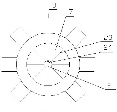
[0027] like image 3 As shown, in actual use, the valve core hole 5 and the center line of the valve body connecting pipe flow channel 15 are located on the same circumferential plane, which ensures that the valve core hole 5 is connected to the valve body during the rotation of the valve core 2. The pipe flow channel 15 can be accurately aligned, thereby ensuring the normal opening of the flow channel; the sliding sleeve hole 4 is parallel to the center line of the valve core hole 5, and the projections on the circumferential plane coincide, ensuring that the sliding sl...
Embodiment 3
[0029] On the basis of Embodiment 2, in this embodiment, preferably, the valve core 2 is divided into two sections connected in sequence, and the outer diameter of the first section close to the end cover 20 > the outer diameter of the first section away from the end cover 20 The outer diameter of the second section, the valve core 2 is axially positioned with the positioning step 17 in the valve body 1 through its first section. The outer diameter of the sliding sleeve 14 is the same as the inner diameter of the valve body 1 , and the inner diameter of the sliding sleeve 14 is the same as the outer diameter of the second section of the valve core 2 . The second section of the spool 2 is provided with a groove 13 near the center of one end of the valve stem 9. The notch of the groove 13 is a rectangle, and the symmetry axis of the rectangle is parallel to the long side and the centerline of the spool hole 5. parallel, and the projections on the circumferential plane coincide. ...
PUM
 Abstract
Description
Claims
Application Information
 - R&D
- Intellectual Property
- Life Sciences
- Materials
- Tech Scout
- Unparalleled Data Quality
- Higher Quality Content
- 60% Fewer Hallucinations
Browse by: Latest US Patents, China's latest patents, Technical Efficacy Thesaurus, Application Domain, Technology Topic, Popular Technical Reports.
© 2025 PatSnap. All rights reserved.Legal|Privacy policy|Modern Slavery Act Transparency Statement|Sitemap|About US| Contact US: help@patsnap.com