Assembly type indoor cable and wire mounting structure

An installation structure and component technology, applied in the direction of electrical components, etc., can solve the problems of no angle adjustment, no height adjustment, inconvenient installation and use of staff, etc., to achieve convenient fixed installation, simple and convenient operation, and increase practicability Effect

Pending Publication Date: 2020-12-29
GOLD MANTIS FINE DECORATION TECH SUZHOU CO LTD
View PDF0 Cites 0 Cited by
  • Summary
  • Abstract
  • Description
  • Claims
  • Application Information

AI Technical Summary

Problems solved by technology

[0004] The first point is that the existing cable fixing bracket adopts a fixed design because of its structure, which makes it impossible for the staff to adjust its height, which brings inconvenience to the installation and use of the staff.
[0005] The second point, the existing cable fixing brackets are generally provided with a plurality of fixing hole slots, and the staff can put a plurality of cables into the corresponding fixing hole slots, and then fix them together, and Although this structure can fix multiple cables at one time, when the staff needs to disassemble or replace one of the cables, they can only open the fixing structure at this time, and then take out the corresponding cable. In this process, other cables will also be unfixed, which will affect the fixing effect of other cables
[0006] The third point is that the existing cable fixing bracket does not have the function of angle adjustment in actual use, which leads to the fact that it can only fix the cable at one position. However, when the staff installs the cable and wire , it is often necessary to consider the space layout, and the direction of cables and wires will be changed at any time. At this time, the fixed cable bracket will not be able to meet the installation needs of the staff.

Method used


Image

  • Assembly type indoor cable and wire mounting structure
  • Assembly type indoor cable and wire mounting structure
  • Assembly type indoor cable and wire mounting structure

Examples


Embodiment Construction

[0029] The following will clearly and completely describe the technical solutions in the embodiments of the present invention with reference to the accompanying drawings in the embodiments of the present invention. Obviously, the described embodiments are only some, not all, embodiments of the present invention. Based on the embodiments of the present invention, all other embodiments obtained by persons of ordinary skill in the art without making creative efforts belong to the protection scope of the present invention.

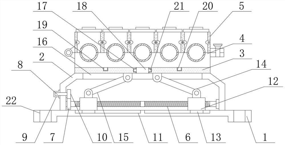
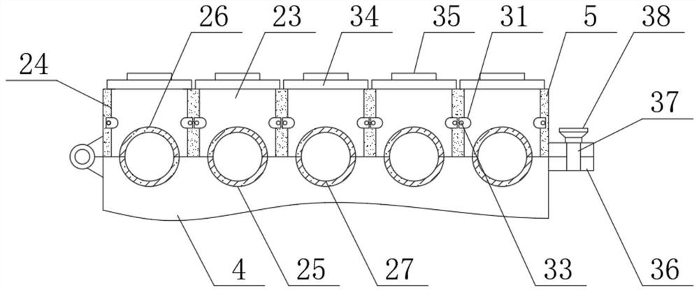
[0030] Such as Figure 1 to Figure 6As shown, in the embodiment of the present invention, a modular indoor cable and wire installation structure includes a bottom plate 1, a bottom box 2 is fixedly installed on the top of the bottom plate 1, and a movable plate 3 is movably connected to the top of the bottom box 2, and the movable plate 3 The top is movably connected with a fixed block 4, the left side of the top of the fixed block 4 is hinged with a movable b...


PUM


Abstract

The invention belongs to the technical field of line installation, and discloses an assembly type indoor cable and wire installation structure, which comprises a bottom plate, wherein a bottom box isfixedly installed at the top of the bottom plate, a movable plate is movably connected to the top of the bottom box, a fixed block is movably connected to the top of the movable plate, a movable blockis hinged to the left side of the top of the fixed block, the bottom of the movable block is movably connected with the top of the fixed block, and a lead screw is movably mounted in the bottom box.By arranging the lead screw, the moving blocks and the inclined rods, when the lead screw rotates, the two moving blocks can move oppositely, at the moment, due to the pushing effect of the two inclined rods, the movable plate, the fixed block and the movable block can integrally move upwards, and then the position height of a first clamping arc and the position height of a second clamping arc arechanged, so that workers can conveniently fix and mount cables at different position heights, and the operation is simple and convenient so as to improve the practicability of the cable and wire mounting structure.

Description

technical field [0001] The invention belongs to the technical field of line installation, in particular to a component type indoor cable and wire installation structure. Background technique [0002] Cables and wires are wire products used to transmit electric energy, information and realize the conversion of electromagnetic energy. Cables and wires in a broad sense are also referred to as cables for short. Cables in a narrow sense refer to insulated cables. The cladding layer, the total protective layer and the outer protective layer. [0003] At present, when the staff is decorating the interior, they often need to install and fix the cables and wires, and when the cables and wires are installed and fixed, they need to use corresponding fixing brackets, and the existing cable fixing brackets are used in actual use. , has the following defects: [0004] First, because the structure of the existing cable fixing bracket adopts a fixed design, the staff cannot adjust its hei...

Claims


Application Information

Patent Timeline
Patent Type & Authority Applications(China)
IPC IPC(8): H02G3/02
CPCH02G3/02
Inventor 王举光张泽永胡健孟小可
Owner GOLD MANTIS FINE DECORATION TECH SUZHOU CO LTD
Why Eureka
Try Eureka