
Rotor structure and motor

A technology of rotor structure and positioning structure, applied in the direction of magnetic circuit shape/style/structure, electrical components, electromechanical devices, etc., can solve problems such as the decline of magnetization performance, achieve good stability, and ensure the effect of magnetic suspension accuracy

Active Publication Date: 2020-12-29
GREE ELECTRIC APPLIANCES INC OF ZHUHAI +1
View PDF6 Cites 0 Cited by
  • Summary
  • Abstract
  • Description
  • Claims
  • Application Information

AI Technical Summary

Problems solved by technology

[0003] The existing permanent magnet is a ring structure with the front and rear short axes cooperating with the permanent magnet. The permanent magnet can be offset along the circumferential direction, while the permanent magnet is in a parallel magnetization mode. Once the permanent magnet produces an offset angle θ, the corresponding magnetization direction is also The θ angle will be generated, and the magnetization performance will decrease

Method used


Image

  • Rotor structure and motor
  • Rotor structure and motor
  • Rotor structure and motor

Examples


Embodiment Construction

[0034] In order to make the purposes, technical solutions and advantages of the embodiments of the present application clearer, the technical solutions in the embodiments of the present application will be clearly and completely described below in conjunction with the drawings in the embodiments of the present application. Obviously, the described embodiments It is a part of the embodiments of this application, but not all of them. Based on the embodiments in the present application, all other embodiments obtained by persons of ordinary skill in the art without making creative efforts belong to the protection scope of the present application.

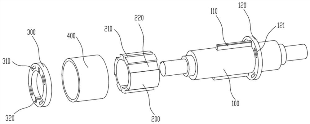
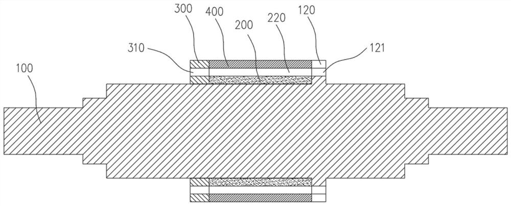
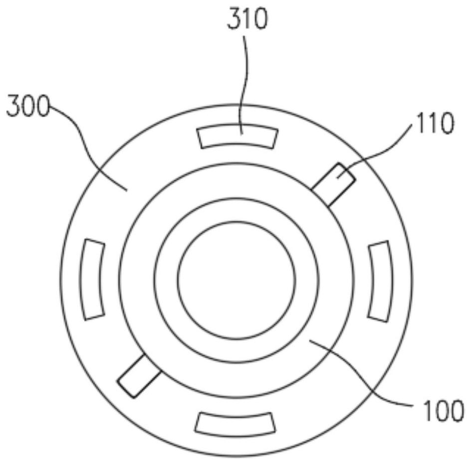
[0035] This solution provides a rotor structure and a motor. The motor is a high-speed permanent magnet motor. The rotor structure includes a mandrel 100 and a permanent magnet 200 for sleeve connection with the mandrel 100. The mandrel 100 adopts an integral structure, replacing the The existing multi-segment structure of the mandrel 1...


PUM


Abstract

The invention generally relates to the technical field of motors, and particularly relates to a rotor structure and a motor. The rotor structure comprises a core shaft and a permanent magnet used forbeing connected with the core shaft in a sleeving manner, the core shaft is an integrated structure and replaces an existing core shaft of a multi-section structure form, coaxiality deviation abnormity is avoided, and suspension precision of the rotor structure is improved. The core shaft is provided with a first positioning structure, the permanent magnet is provided with a second positioning structure, and the first positioning structure is used for being connected with the second positioning structure in a matched mode so as to limit circumferential rotation of the permanent magnet, preventa magnetizing direction of the permanent magnet from deviating and guarantee operation reliability of the rotor structure.

Description

technical field [0001] The present application generally relates to the field of motor technology, and in particular, relates to a rotor structure and a motor. Background technique [0002] The magnetic levitation motor uses the electromagnetic force of the magnetic levitation bearing to suspend the motor rotor in the air, so that there is no mechanical contact between the motor rotor and the motor stator, and there is no mechanical friction. It is a low-loss, high-performance motor. [0003] The existing permanent magnet is a ring structure with the front and rear short axes cooperating with the permanent magnet. The permanent magnet can be offset along the circumferential direction, while the permanent magnet is in a parallel magnetization mode. Once the permanent magnet produces an offset angle θ, the corresponding magnetization direction is also A θ angle will be generated, and the magnetization performance will decrease. Contents of the invention [0004] A series of...

Claims


Application Information

Patent Timeline
IPC IPC(8): H02K1/27H02K1/24H02K1/32
CPCH02K1/27H02K1/24H02K1/325
Inventor 林学明伍尚权王周叶曹俊辉王志强
Owner GREE ELECTRIC APPLIANCES INC OF ZHUHAI
Learn More