Water cooling head

A technology of water cooling head and water inlet channel, which is applied in the direction of cooling/ventilation/heating transformation, electrical components, electrical equipment structural parts, etc., and can solve problems such as insufficient cooling liquid storage space and insufficient cooling liquid supply

Pending Publication Date: 2020-12-29
泽鸿(广州)电子科技有限公司
View PDF0 Cites 0 Cited by
  • Summary
  • Abstract
  • Description
  • Claims
  • Application Information

AI Technical Summary

Problems solved by technology

[0004] However, when the existing heat dissipation modules transport the cooling liquid to the space for absorbing heat energy in the electronic components to be dissipated, the storage space for the cooling liquid is often insufficient, resulting in insufficient cooling liquid supply when the position of the water cooling head is changed or moved. The problem

Method used


Image

  • Water cooling head
  • Water cooling head
  • Water cooling head

Examples


Embodiment Construction

[0092] The implementation of the present invention will be described below through specific specific examples, and those skilled in the art can easily understand other advantages and effects of the present invention from the content disclosed in this description, and can also be implemented or implemented through other different specific examples. application.

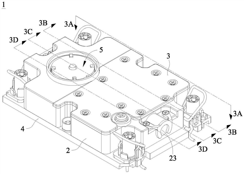
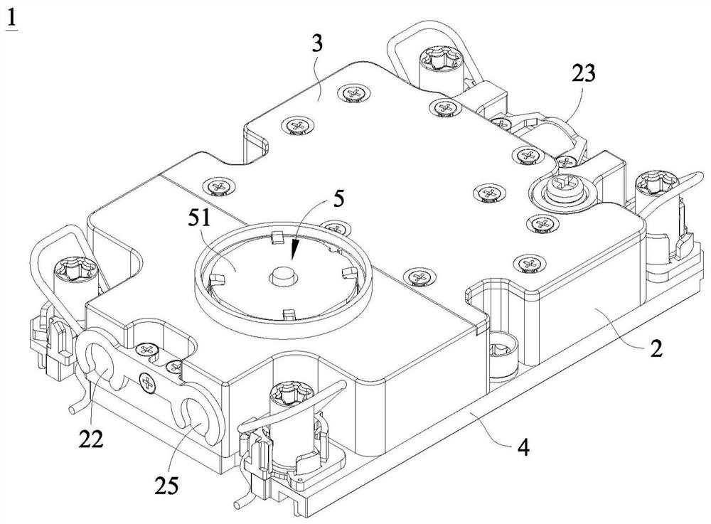
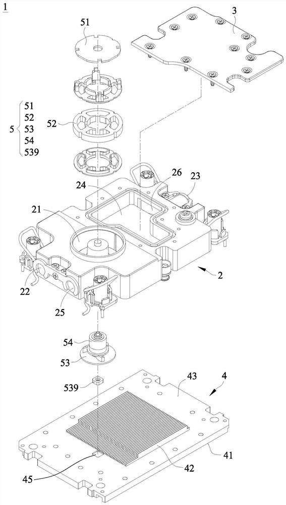
[0093] The water-cooled head provided by the present invention can be installed in electronic devices such as computer hosts or servers, and the inside of the water-cooled head can be filled with a working medium (such as cooling liquid), and the working medium can absorb heat generated by heat sources (such as electronic components such as chips or memories). The heat energy generated, the heated working medium can be sent to the condensing device for cooling, and the cooled working medium can be sent back to the water cooling head for the next heat absorption and circulation.

[0094] Please also see Figure 1A to F...


PUM


Abstract

The invention provides a water cooling head. The water cooling head comprises a heat absorption space, a heat transfer structure, a cavity and a communication structure. The heat absorption space is used for allowing a working medium to flow therein, the heat transfer structure is arranged on a base, is positioned in the heat absorption space and is used for transferring heat energy generated by aheat source in contact with the base to the working medium, the cavity is positioned in the shell above the heat transfer structure and is separated from the heat absorption space, and the communication structure is arranged in the shell so as to communicate the cavity with the heat absorption space.

Description

technical field [0001] The invention relates to the field of heat dissipation, in particular to a water cooling head. Background technique [0002] According to modern requirements, computers and various electronic devices are developing rapidly and their performance is constantly improving. However, in the process, heat dissipation problems caused by high-performance hardware also follow. Generally speaking, computers and various electronic devices usually use heat dissipation components to dissipate heat. For example, heat dissipation paste or heat sinks are attached to the electronic components to be dissipated, so as to absorb and dissipate heat. However, the effect of this heat dissipation method is limited, so a heat dissipation module using a liquid cooling method has been developed. [0003] Existing heat dissipation modules that use liquid cooling generally use coolant to absorb heat energy. For example, the coolant is fluidly connected to the electronic components...

Claims


Application Information

Patent Timeline
Patent Type & Authority Applications(China)
IPC IPC(8): H05K7/20
CPCH05K7/20254H05K7/20272
Inventor 陈建安陈建佑陈韦豪
Owner 泽鸿(广州)电子科技有限公司
Why Eureka
Try Eureka