Staging operation unit

a technology of operation unit and staging unit, which is applied in the field of staging operation unit, can solve the problems of damage in the members and gap may be created between, and achieve the effects of preventing damage in the members, high staging capability, and high operability

Inactive Publication Date: 2014-10-02
ORMON CORP
View PDF3 Cites 0 Cited by
  • Summary
  • Abstract
  • Description
  • Claims
  • Application Information

AI Technical Summary

Benefits of technology

[0012]For this reason, by providing the accessory on the convex portion and further providing the pushed-in movable member on the rotary member, even when the outer diameters of the convex portion and the rotary member become large, the pushed-in movable member is prevented from inclining with respect to the direction parallel to the rotation axis. With this arrangement, it is prevented that foreign matter such as duct gets in a gap, between the members, created by the inclination of the pushed-in movable member with respect to the direction parallel to the rotation axis, and it is prevented that a damage is created in the member by forcefully performing the push-down operation when the pushed-in movable member is inclined.
[0013]According to the above configuration, a staging operation unit having high operability and high staging capability can be realized in which the same rotary member has a rotary operation function and a push-in operation function, and further has an accessory function. In addition, since at least a part of the accessory is disposed in the convex portion on which the bearing member is assembled, effective staging can be provided at the center of the staging operation unit.

Problems solved by technology

However, in the case that a staging operation unit having a push-down operation function (button operation function) is made large, when the user performs a push-in operation on a position decentered from the center of an operation button, a pushed-in movable member to be moved by the push-in operation moves being inclined with respect to the push-in direction; thus, a gap may be created between the pushed-in movable member and other members, whereby foreign matter such as dust enters the gap, or the contact of the pushed-in movable member and other members may create damage in the members.

Method used


Image

  • Staging operation unit
  • Staging operation unit
  • Staging operation unit

Examples


Embodiment Construction

[0032]Embodiments of the present invention will be described with reference to the drawings. In embodiments of the invention, numerous specific details are set forth in order to provide a more thorough understanding of the invention. However, it will be apparent to one of ordinary skill in the art that the invention may be practiced without these specific details. In other instances, well-known features have not been described in detail to avoid obscuring the invention.

[0033](1-1. General Structure of Pachinko Machine 1)

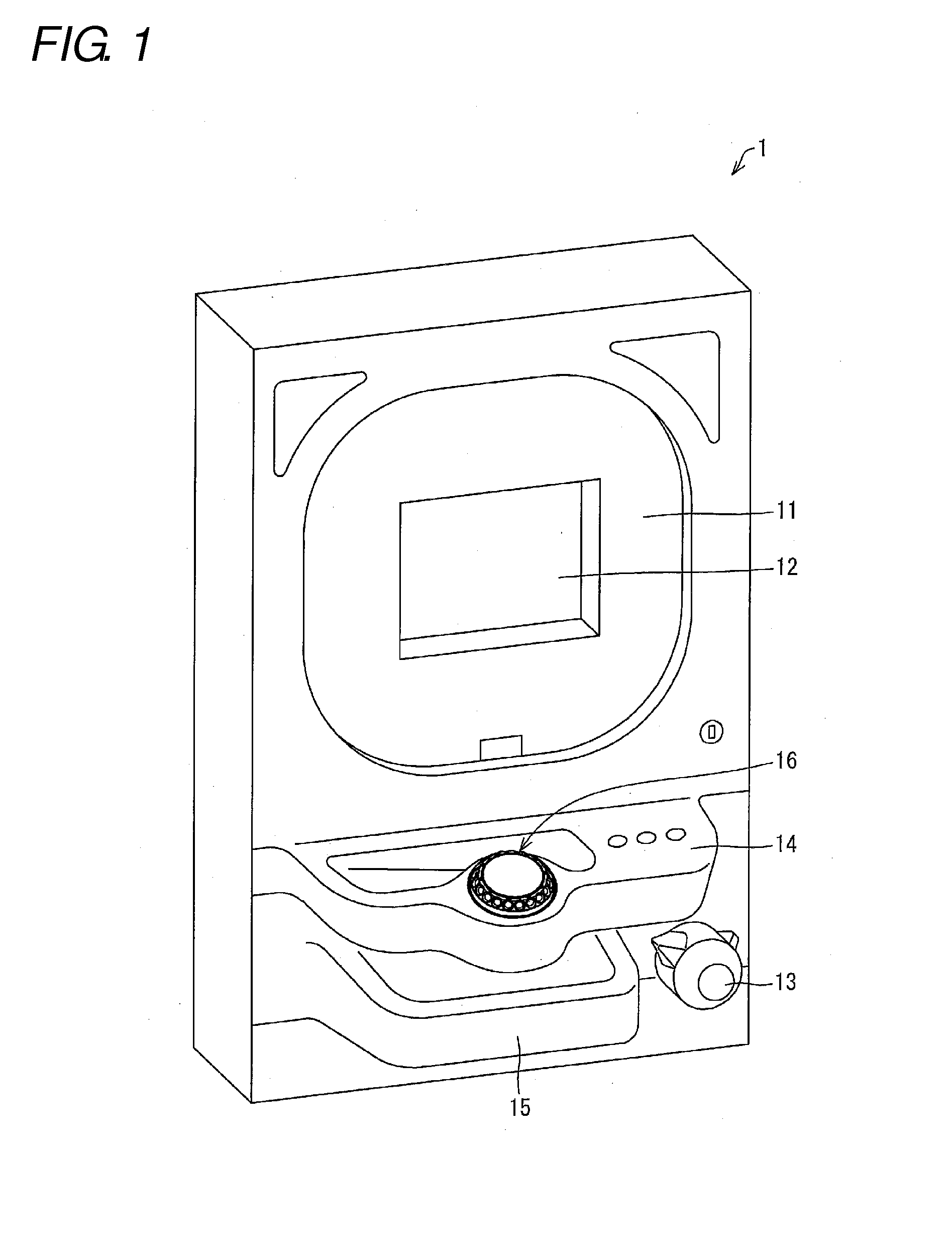
[0034]FIG. 1 is an explanatory diagram illustrating a configuration of a pachinko machine 1 as an amusement machine according to one or more embodiments of the present invention. Although an description will be made of one or more embodiments of the present invention being applied to a pachinko machine as an example of the amusement machine, the application of the present invention is not limited to this case, and one or more embodiments of the present invention can ...


PUM


Abstract

A staging operation unit has a base member having a convex portion, a rotary member, a bearing member fixed on the convex portion, that has the rotary member mounted thereon rotatably with respect to the base member, an accessory. The rotary member has a rotatable base member mounted on the bearing member, a pushed-in movable member that accepts a push-in operation, with respect to the rotatable base member, in a direction along a rotation axis of the bearing member, a rotary operation detection unit that detects rotation of the rotary member and output a signal corresponding to a result of the detection of the rotation to outside, and a push-in operation detection unit that detects the push-in operation of the pushed-in movable member and output a signal corresponding to a result of the detection of the push-in operation to outside.

Description

BACKGROUND[0001]1. Field[0002]The present invention relates to a staging operation unit for a user of various types of devices to perform an operation input.[0003]2. Related Art[0004]Conventionally, there are known amusement machines such as pachinko machines, slot machines, and game machines which are equipped with a staging operation unit for a user to perform selection of staging modes and display images and perform other functions.[0005]For example, Japanese Unexamined Patent Publication No. 2012-066115 (published on Apr. 5, 2012) discloses an amusement machine having an operation button equipped with a revolving light therein.[0006]In addition, Japanese Unexamined Patent Publication No. 2012-110372 (published on Jun. 14, 2012) discloses an amusement machine which is equipped with a circular ring-shaped dial operation unit and a cylinder shaped press operation unit housed inside the circular ring of the circular ring-shaped dial operation unit.SUMMARY[0007]In amusement machines ...

Claims


Application Information

Patent Timeline
Patent Type & Authority Applications(United States)
IPC IPC(8): G06F3/02A63F11/00
CPCA63F11/00G06F3/02G05G1/02G05G1/10
Inventor ONO, TAKAHIROFURUTA, TAKEHIKO
Owner ORMON CORP
Why Eureka
Try Eureka