Inflatable vaginal dilator
A vaginal dilator and inflatable technology, which is applied in surgery and other directions, can solve the problems of small internal space of the vaginal dilator, narrow inspection field of view, inconvenient use, etc., and achieve large internal space, low manufacturing cost, and stable expansion structure Effect
- Summary
- Abstract
- Description
- Claims
- Application Information
AI Technical Summary
Problems solved by technology
Method used
Image
Examples
Embodiment 1
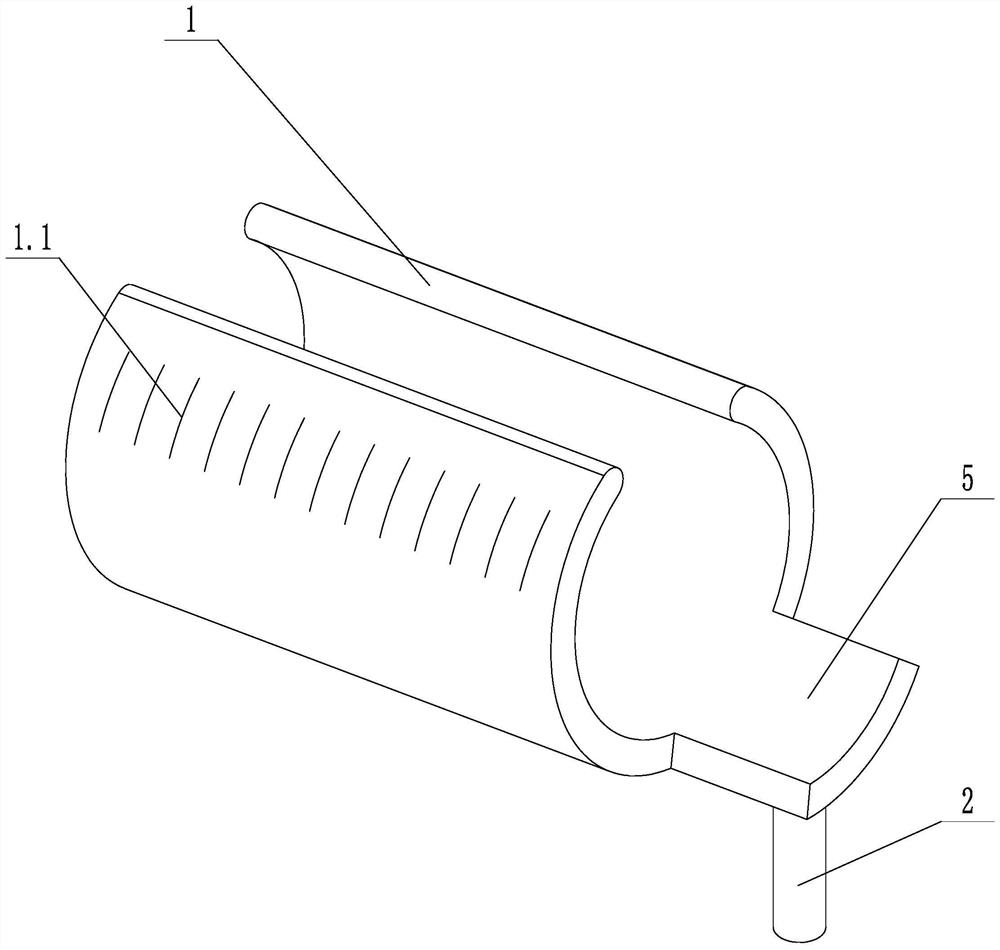
[0026]Such asfigure 1 As shown, an inflatable vaginal dilator includes a support body 1 and an inflation tube 2. The cross section of the support body 1 is a C-shaped structure, the support body 1 is provided with an air cavity, and the inflation tube 2 is in communication with the air cavity. The supporting body 1 is provided with a connecting block 5, the connecting block 5 is relatively difficult to deform, and the inflation tube 2 is arranged on the connecting block 5. A number of anti-slip protrusions 1.1 arranged longitudinally are provided on the outer surface of the supporting body 1.
[0027]In the above technical solution, the support body 1 can be contracted when it is not inflated, and its appearance is small, so that it can be inserted into the body. When the support body 1 extends into the body, the air cavity is inflated through the inflation tube 2 to expand the support body 1 to form C形结构。 Shape structure. The open-ended vaginal expander has a large internal space, has...
Embodiment 2
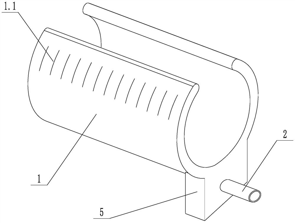
[0029]Such asfigure 2 As shown, on the basis of Embodiment 1, the connecting block 5 is laterally arranged at one end of the supporting body 1. The supporting body 1 is provided with several supporting bars arranged longitudinally, and the supporting bars are evenly distributed along the circumference of the supporting body 1. The connecting block 5 can make the connecting block 5 play a positioning role. The support bar can ensure the structural strength of the longitudinal support body 1 and increase the effect of expanding the shadow.
Embodiment 3
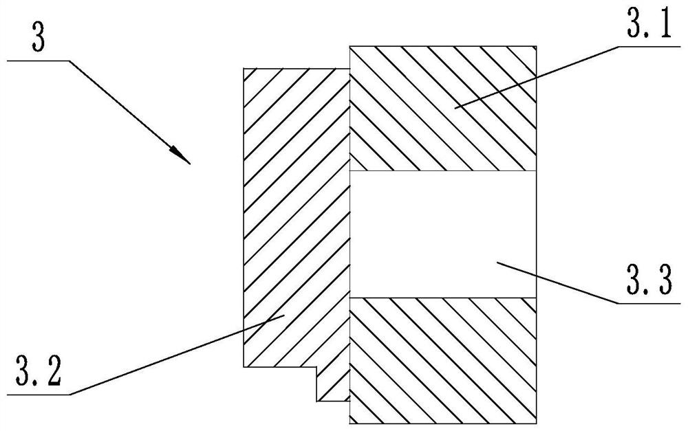
[0031]Such asimage 3 As shown, on the basis of Embodiment 1, a one-way valve 3 is provided in the inflation tube 2. A one-way valve 3 is provided in the inflation tube 2. The one-way valve 3 includes a communicating block 3.1 and a sealing block 3.2. The communicating block 3.1 is provided with a communicating hole 3.3. The end face of the sealing block 3.2 is in close contact with the end face of the communicating block 3.1, and one side of the sealing block 3.2 is fixed to the communicating block 3.1 . The connection between the sealing block 3.2 and the connecting block 3.1 has a certain degree of elasticity. The structure can pull out the inflation device after inflating the vaginal expander, which is convenient for doctors to perform diagnosis and treatment operations. The structure can pull out the inflation device after inflating the vaginal expander, which is convenient for doctors to perform diagnosis and treatment operations. The one-way valve 3 has a one-way ventilation f...
PUM
 Abstract
Description
Claims
Application Information
 - R&D
- Intellectual Property
- Life Sciences
- Materials
- Tech Scout
- Unparalleled Data Quality
- Higher Quality Content
- 60% Fewer Hallucinations
Browse by: Latest US Patents, China's latest patents, Technical Efficacy Thesaurus, Application Domain, Technology Topic, Popular Technical Reports.
© 2025 PatSnap. All rights reserved.Legal|Privacy policy|Modern Slavery Act Transparency Statement|Sitemap|About US| Contact US: help@patsnap.com


